"An application server can be either a software framework that provides a generalized approach to creating an application-server implementation, without regard to what the application functions are, or the server portion of a specific implementation instance. In either case, the server's function is dedicated to the efficient execution of procedures (programs, routines, scripts) for supporting its applied applications." [Application server. Wikipedia]
"Hardware requirement for servers vary, depending on the server application. Absolute CPU speed is not quite as critical to a server as it is to a desktop machine. Servers' duties to provide service to many users over a network lead to different requirements such as fast network connections and high I/ O throughout. Since servers are usually accessed over a network, they may run in headless mode without a monitor or input device. Processes that are not needed for the server's function are not used. Many servers do not have a graphical user interface (GUI) as it is unnecessary and consumes resources that could be allocated elsewhere. Similarly, audio and USB interfaces may be omitted. ...
As servers need a stable power supply, good Internet access, increased security and are also noisy, it is usual to store them in dedicated server centers or special rooms. This requires reducing the power consumption, as the extra energy used generates more heat thus causing the temperature in the room to exceed acceptable limits; hence normally, server rooms are equipped with air conditioning devices. Server casings are usually flat and wide (typically measured in "rack units"), adapted to store many devices next to each other in a server rack. Unlike ordinary computers, servers usually can be configured, powered up and down or rebooted remotely, using out-of-band management, typically based on IPMI." [Server (computing). Wikipedia]
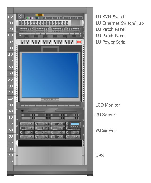
A rack diagram is useful for designing and documenting of network rack server equipment (19-inch or 23-inch rack, rack cabinet, rack unit, network switch, router, KVM switch, server) of data centers, ISP facilities and corporate server rooms.
This application server rack diagram example was created using the ConceptDraw PRO diagramming and vector drawing software extended with the Rack Diagrams solution from the Computer and Networks area of ConceptDraw Solution Park.
"Hardware requirement for servers vary, depending on the server application. Absolute CPU speed is not quite as critical to a server as it is to a desktop machine. Servers' duties to provide service to many users over a network lead to different requirements such as fast network connections and high I/ O throughout. Since servers are usually accessed over a network, they may run in headless mode without a monitor or input device. Processes that are not needed for the server's function are not used. Many servers do not have a graphical user interface (GUI) as it is unnecessary and consumes resources that could be allocated elsewhere. Similarly, audio and USB interfaces may be omitted. ...
As servers need a stable power supply, good Internet access, increased security and are also noisy, it is usual to store them in dedicated server centers or special rooms. This requires reducing the power consumption, as the extra energy used generates more heat thus causing the temperature in the room to exceed acceptable limits; hence normally, server rooms are equipped with air conditioning devices. Server casings are usually flat and wide (typically measured in "rack units"), adapted to store many devices next to each other in a server rack. Unlike ordinary computers, servers usually can be configured, powered up and down or rebooted remotely, using out-of-band management, typically based on IPMI." [Server (computing). Wikipedia]
A rack diagram is useful for designing and documenting of network rack server equipment (19-inch or 23-inch rack, rack cabinet, rack unit, network switch, router, KVM switch, server) of data centers, ISP facilities and corporate server rooms.
This application server rack diagram example was created using the ConceptDraw PRO diagramming and vector drawing software extended with the Rack Diagrams solution from the Computer and Networks area of ConceptDraw Solution Park.
Rack diagram
Server
Rack Diagrams visualize the rack mounting of computer hardware and network equipment as the drawing of frontal view of the rack with equipment installed.
They are used for choosing the equipment or racks to buy, and help to organize equipment on the racks virtually, without the real installation.
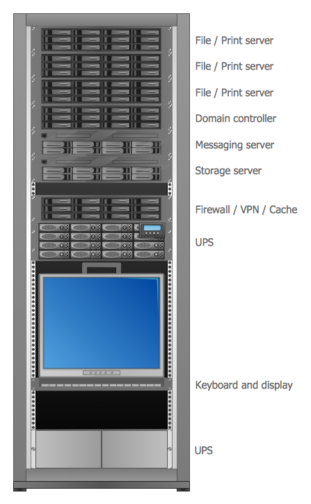
"A server is a system (software and suitable computer hardware) that responds to requests across a computer network to provide, or help to provide, a network service. Servers can be run on a dedicated computer, which is also often referred to as "the server", but many networked computers are capable of hosting servers. In many cases, a computer can provide several services and have several servers running. ...
Servers often provide essential services across a network, either to private users inside a large organization or to public users via the Internet. Typical computing servers are database server, file server, mail server, print server, web server, gaming server, application server..." [Server (computing). Wikipedia]
This network server rack diagram example was created using the ConceptDraw PRO diagramming and vector drawing software extended with the Rack Diagrams solution from the Computer and Networks area of ConceptDraw Solution Park.
They are used for choosing the equipment or racks to buy, and help to organize equipment on the racks virtually, without the real installation.
"A server is a system (software and suitable computer hardware) that responds to requests across a computer network to provide, or help to provide, a network service. Servers can be run on a dedicated computer, which is also often referred to as "the server", but many networked computers are capable of hosting servers. In many cases, a computer can provide several services and have several servers running. ...
Servers often provide essential services across a network, either to private users inside a large organization or to public users via the Internet. Typical computing servers are database server, file server, mail server, print server, web server, gaming server, application server..." [Server (computing). Wikipedia]
This network server rack diagram example was created using the ConceptDraw PRO diagramming and vector drawing software extended with the Rack Diagrams solution from the Computer and Networks area of ConceptDraw Solution Park.
Rack diagram
"A server is a system (software and suitable computer hardware) that responds to requests across a computer network to provide, or help to provide, a network service. Servers can be run on a dedicated computer, which is also often referred to as "the server", but many networked computers are capable of hosting servers. In many cases, a computer can provide several services and have several servers running.
Servers operate within a client-server architecture. Servers are computer programs running to serve the requests of other programs, the clients. Thus, the server performs some tasks on behalf of clients. The clients typically connect to the server through the network but may run on the same computer. In the context of Internet Protocol (IP) networking, a server is a program that operates as a socket listener.
Servers often provide essential services across a network, either to private users inside a large organization or to public users via the Internet. Typical computing servers are database server, file server, mail server, print server, web server, gaming server, application server, or some other kind of server.
Numerous systems use this client / server networking model including Web sites and email services. An alternative model, peer-to-peer networking enables all computers to act as either a server or client as needed." [Server (computing). Wikipedia]
The UML component diagram example "Start server" was created using the ConceptDraw PRO diagramming and vector drawing software extended with the Rapid UML solution from the Software Development area of ConceptDraw Solution Park.
UML component diagram

 Rack Diagrams
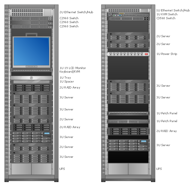
The Rack Diagrams solution, including a vector stencil library, a collection of samples and a quick-start template, can be useful for all who deal with computer networks. Choosing any of the 54 library's vector shapes, you can design various types of Rack diagrams or Server rack diagrams visualizing 19" rack mounted computers and servers.
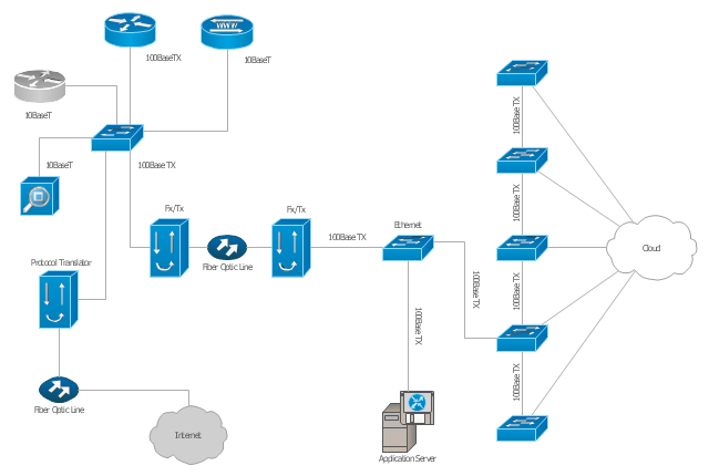
"A computer network diagram is a schematic depicting the nodes and connections amongst nodes in a computer network or, more generally, any telecommunications network. ...
Depending on whether the diagram is intended for formal or informal use, certain details may be lacking and must be determined from context. ...
At different scales diagrams may represent various levels of network granularity. At the LAN level, individual nodes may represent individual physical devices, such as hubs or file servers, while at the WAN level, individual nodes may represent entire cities. In addition, when the scope of a diagram crosses the common LAN/ MAN/ WAN boundaries, representative hypothetical devices may be depicted instead of showing all actually existing nodes." [Computer network diagram. Wikipedia]
The Cisco computer network diagram example "Network organization chart" was created using the ConceptDraw PRO diagramming and vector drawing software extended with the Cisco Network Diagrams solution from the Computer and Networks area of ConceptDraw Solution Park.
Cisco network diagram
The vector stencils library "Bank UML deployment diagram" contains 10 shapes for drawing UML deployment diagrams.
Use it for object-oriented modeling of your bank information system.
"A deployment diagram in the Unified Modeling Language models the physical deployment of artifacts on nodes. To describe a web site, for example, a deployment diagram would show what hardware components ("nodes") exist (e.g., a web server, an application server, and a database server), what software components ("artifacts") run on each node (e.g., web application, database), and how the different pieces are connected (e.g. JDBC, REST, RMI).
The nodes appear as boxes, and the artifacts allocated to each node appear as rectangles within the boxes. Nodes may have subnodes, which appear as nested boxes. A single node in a deployment diagram may conceptually represent multiple physical nodes, such as a cluster of database servers.
There are two types of Nodes:
1. Device Node.
2. Execution Environment Node.
Device nodes are physical computing resources with processing memory and services to execute software, such as typical computers or mobile phones. An execution environment node (EEN) is a software computing resource that runs within an outer node and which itself provides a service to host and execute other executable software elements." [Deployment diagram. Wikipedia]
This example of UML deployment diagram symbols for the ConceptDraw PRO diagramming and vector drawing software is included in the ATM UML Diagrams solution from the Software Development area of ConceptDraw Solution Park.
UML deployment diagram symbols

"A deployment diagram in the Unified Modeling Language models the physical deployment of artifacts on nodes. To describe a web site, for example, a deployment diagram would show what hardware components ("nodes") exist (e.g., a web server, an application server, and a database server), what software components ("artifacts") run on each node (e.g., web application, database), and how the different pieces are connected (e.g. JDBC, REST, RMI)." [Deployment diagram. Wikipedia]
This UML deployment diagram example was created using the ConceptDraw PRO diagramming and vector drawing software extended with the Rapid UML solution from the Software Development area of ConceptDraw Solution Park.
This UML deployment diagram example was created using the ConceptDraw PRO diagramming and vector drawing software extended with the Rapid UML solution from the Software Development area of ConceptDraw Solution Park.
UML deployment diagram

Diagramming Software for Design UML Collaboration Diagrams


UML Diagram

"A computer network diagram is a schematic depicting the nodes and connections amongst nodes in a computer network or, more generally, any telecommunications network. ...
Depending on whether the diagram is intended for formal or informal use, certain details may be lacking and must be determined from context. ...
At different scales diagrams may represent various levels of network granularity. At the LAN level, individual nodes may represent individual physical devices, such as hubs or file servers, while at the WAN level, individual nodes may represent entire cities. In addition, when the scope of a diagram crosses the common LAN/ MAN/ WAN boundaries, representative hypothetical devices may be depicted instead of showing all actually existing nodes." [Computer network diagram. Wikipedia]
The Cisco computer network diagram example "Network organization chart" was created using the ConceptDraw PRO diagramming and vector drawing software extended with the Cisco Network Diagrams solution from the Computer and Networks area of ConceptDraw Solution Park.
Depending on whether the diagram is intended for formal or informal use, certain details may be lacking and must be determined from context. ...
At different scales diagrams may represent various levels of network granularity. At the LAN level, individual nodes may represent individual physical devices, such as hubs or file servers, while at the WAN level, individual nodes may represent entire cities. In addition, when the scope of a diagram crosses the common LAN/ MAN/ WAN boundaries, representative hypothetical devices may be depicted instead of showing all actually existing nodes." [Computer network diagram. Wikipedia]
The Cisco computer network diagram example "Network organization chart" was created using the ConceptDraw PRO diagramming and vector drawing software extended with the Cisco Network Diagrams solution from the Computer and Networks area of ConceptDraw Solution Park.
Cisco network diagram
Cisco Products Additional. Cisco icons, shapes, stencils and symbols

"The client–server model of computing is a distributed application structure that partitions tasks or workloads between the providers of a resource or service, called servers, and service requesters, called clients. Often clients and servers communicate over a computer network on separate hardware, but both client and server may reside in the same system. A server host runs one or more server programs which share their resources with clients. A client does not share any of its resources, but requests a server's content or service function. Clients therefore initiate communication sessions with servers which await incoming requests.
Examples of computer applications that use the client–server model are Email, network printing, and the World Wide Web." [Client–server model. Wikipedia]
The UML communication diagram example "Client server access" was created using the ConceptDraw PRO diagramming and vector drawing software extended with the Rapid UML solution from the Software Development area of ConceptDraw Solution Park.
UML communication diagram

 Computer Network Diagrams
Computer Network Diagrams solution extends ConceptDraw DIAGRAM software with samples, templates and libraries of vector icons and objects of computer network devices and network components to help you create professional-looking Computer Network Diagrams, to plan simple home networks and complex computer network configurations for large buildings, to represent their schemes in a comprehensible graphical view, to document computer networks configurations, to depict the interactions between network's components, the used protocols and topologies, to represent physical and logical network structures, to compare visually different topologies and to depict their combinations, to represent in details the network structure with help of schemes, to study and analyze the network configurations, to communicate effectively to engineers, stakeholders and end-users, to track network working and troubleshoot, if necessary.
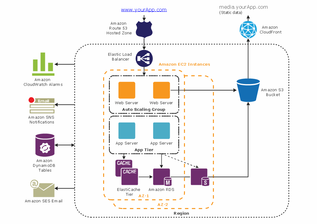
Diagramming tool - Amazon Web Services and Cloud Computing Diagrams
- Application server rack diagram
- Application server rack diagram | Server | UML component diagram ...
- Visio Application Server Diagram
- Application server rack diagram | Typical Rack Sever
- Application Server Architecture Diagram
- Application server rack diagram | Rack Diagrams | Server hardware ...
- Web Server Application Server Architecture Diagram
- Server | Rack Diagrams | UML Diagram | What Are The Examples Of ...
- Network Glossary Definition | Application server rack diagram ...
- Application Server Architecture Diagram With Bulk Email Service
- Web Server And Application Server Architecture Diagram
- Diagram Server
- Rack Diagrams | Server hardware - Rack diagram | Rack diagrams ...
- Simple Diagram Illustrating Application Server
- Computer Server Diagram
- UML Deployment Diagram
- Rack diagrams - Vector stencils library | Cabinet Design Software ...
- Workflow Application | Amazon Web Services Diagrams ...
- Rack diagrams - Vector stencils library
- Rack diagrams - Vector stencils library | Server hardware - Rack ...