The vector stencils library "EPC diagrams" contains 23 EPC symbols.
Use it for drawing event-driven process chain (EPC) diagrams in the ConceptDraw PRO diagramming and vector drawing software extended with the Event-driven Process Chain Diagrams solution from the Business Processes area of ConceptDraw Solution Park.
www.conceptdraw.com/ solution-park/ business-process-EPC
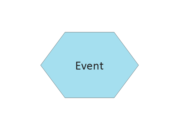
Event
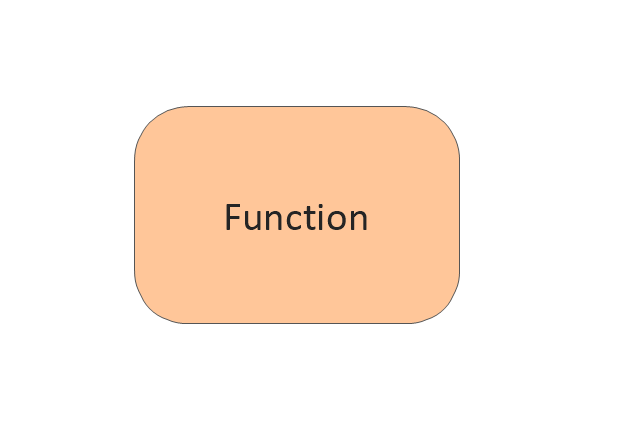
Function
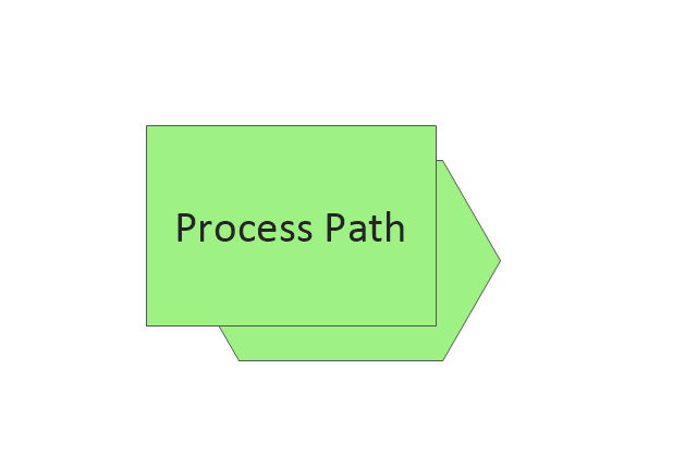
Process path
XOR operator

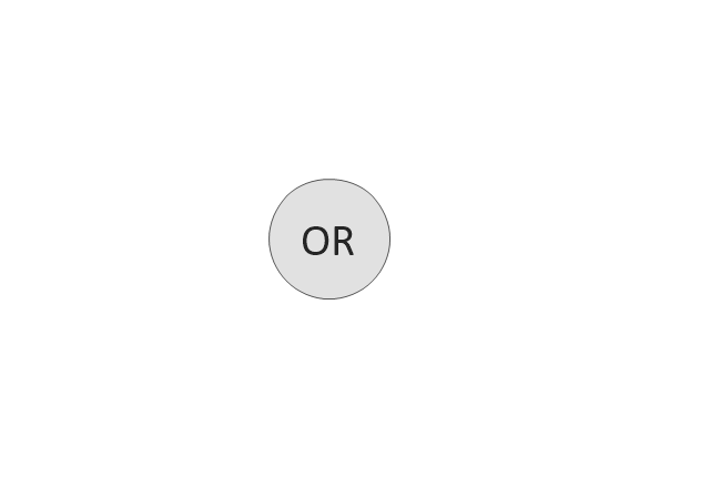
OR operator
AND operator

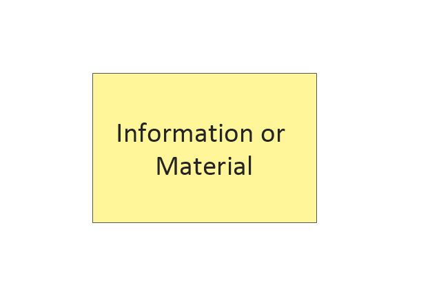
Information/ Material Object
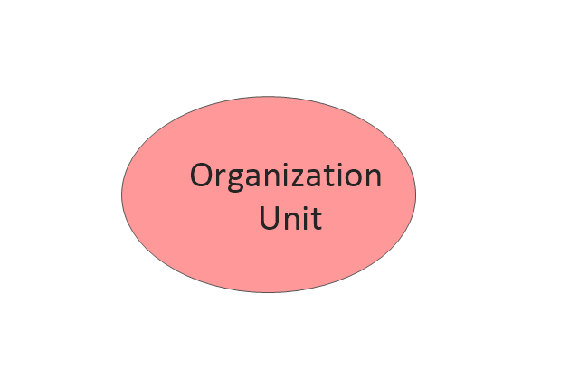
Organization Unit
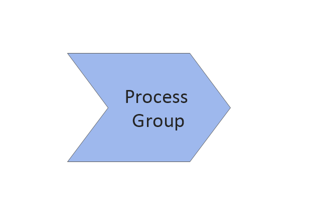
Process Group
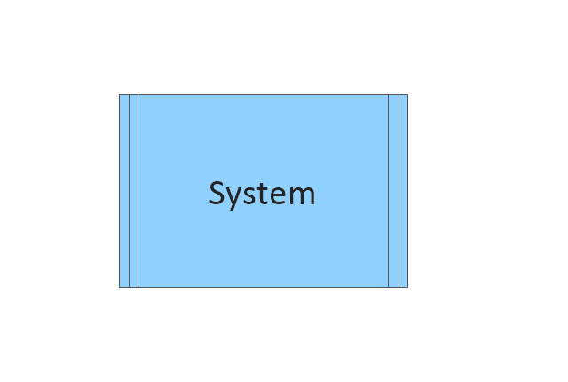
System
Comment 1
Comment 2
Control flow (Direct)
-epc-diagrams---vector-stencils-library.png--diagram-flowchart-example.png)
Information flow (Direct)
-epc-diagrams---vector-stencils-library.png--diagram-flowchart-example.png)
Organiztion unit assignment (Direct)
-epc-diagrams---vector-stencils-library.png--diagram-flowchart-example.png)
Control flow (Smart)
-epc-diagrams---vector-stencils-library.png--diagram-flowchart-example.png)
Information flow (Smart)
-epc-diagrams---vector-stencils-library.png--diagram-flowchart-example.png)
Organiztion unit assignment (Smart)
-epc-diagrams---vector-stencils-library.png--diagram-flowchart-example.png)
Information
Enterprise Area
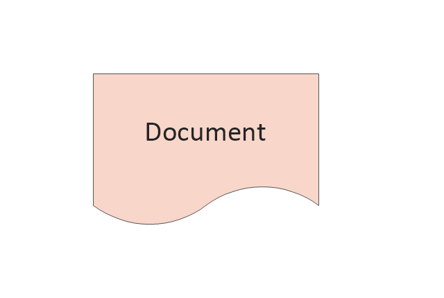
Document
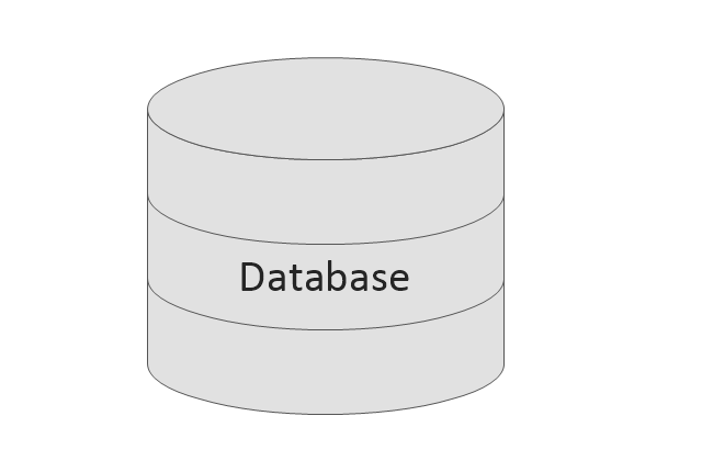
Database
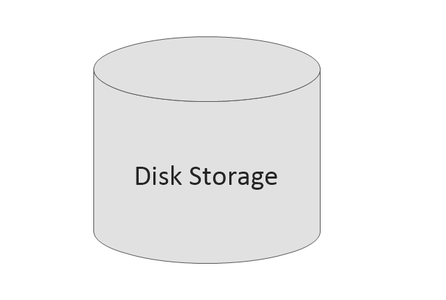
Disk Storage
This interactive voice response (IVR) diagram sample depicts the architecture of IVR systems. It was designed on the base of the Wikimedia Commons file: IVR-Systemarchitektur.png. [commons.wikimedia.org/ wiki/ File:IVR-Systemarchitektur.png]
This file is licensed under the Creative Commons Attribution-Share Alike 3.0 Unported license. [creativecommons.org/ licenses/ by-sa/ 3.0/ deed.en]
"DTMF decoding and speech recognition are used to interpret the caller's response to voice prompts. DTMF tones are entered via the telephone keypad. ...
Other technologies include using text-to-speech (TTS) to speak complex and dynamic information, such as e-mails, news reports or weather information. TTS is computer generated synthesized speech that is no longer the robotic voice traditionally associated with computers. Real voices create the speech in fragments that are spliced together (concatenated) and smoothed before being played to the caller.
An IVR can be deployed in several ways:
1. Equipment installed on the customer premises.
2. Equipment installed in the PSTN (public switched telephone network).
3. Application service provider (ASP) / hosted IVR.
IVR can be used to provide a more sophisticated voice mail experience to the caller. ...
An automatic call distributor (ACD) is often the first point of contact when calling many larger businesses. ...
IVR call flows are created in a variety of ways. A traditional IVR depended upon proprietary programming or scripting languages, whereas modern IVR applications are generated in a similar way to Web pages, using standards such as VoiceXML, CCXML, SRGS and SSML. ...
In telecommunications, an audio response unit (ARU) is a device that provides synthesized voice responses to DTMF keypresses by processing calls based on (a) the call-originator input, (b) information received from a database, and (c) information in the incoming call, such as the time of day.
ARUs increase the number of information calls handled and provide consistent quality in information retrieval." [Interactive voice response. Wikipedia]
The IVR diagram example "IVR systems architecture" was designed using ConceptDraw PRO diagramming and vector drawing software extended with the Interactive Voice Response Diagrams solution from the Computer and Networks area of ConceptDraw Solution Park.
IVR diagram

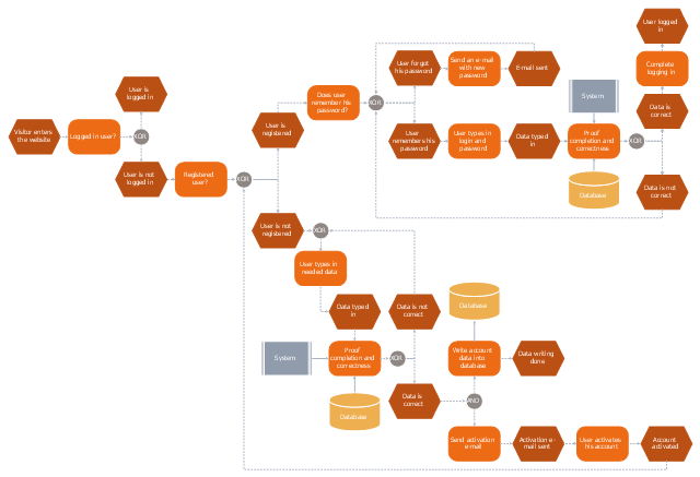
"In computer security, a login or logon refers to the credentials required to obtain access to a computer system or other restricted area. Logging in or on and signing in or on is the process by which individual access to a computer system is controlled by identifying and authenticating the user through the credentials presented by the user.
Once a user has logged in, they can then log out or log off when access is no longer needed. To log out is to close off one's access to a computer system after having previously logged in." [Login. Wikipedia]
The event-driven process chain (EPC) flowchart example "Login and registration processing" was created using the ConceptDraw PRO diagramming and vector drawing software extended with the Event-driven Process Chain Diagrams solution from the Business Processes area of ConceptDraw Solution Park.
EPC flowchart
The business processes modeling (BPM) flowchart sample "Event-driven process chain (EPC) diagram" was created on the base of illustration from "Methods for the specification and verification of business processes. 19 - Event-driven process chains. Roberto Bruni. 2011".
"An Event-driven Process Chain (EPC) is a
particular type of flow-chart that can be used for configuring an Enterprise Resource Planning (ERP) implementation.
Supported by many tools (e.g. SAP R/ 3).
EPC Markup Language available (EPML)
as interchange format. ...
EPC overview.
Important notation to model the domain aspects of business processes.
Rather informal notation.
EPC focus is on representing domain concepts and processes (not their formal aspects and technical realization).
It can be used to drive the modeling, analysis and redesign of business process." [cli.di.unipi.it/ ~rbruni/ MPB-12/ 19-EPC.pdf]
The event-driven process chain (EPC) diagram example was drawn using the ConceptDraw PRO diagramming and vector drawing software extended with the Event-driven Process Chain Diagrams solution from the Business Processes area of ConceptDraw Solution Park.
EPC flow chart
-diagram.png--diagram-flowchart-example.png)
This vector stencils library contains 47 SysML activity diagram symbols.
Use it to design your SysML activity diagrams using ConceptDraw PRO diagramming and vector drawing software.
"Activity diagrams are constructed from a limited number of shapes, connected with arrows. The most important shape types:
- rounded rectangles represent actions;
- diamonds represent decisions;
- bars represent the start (split) or end (join) of concurrent activities;
- a black circle represents the start (initial state) of the workflow;
- an encircled black circle represents the end (final state).
Arrows run from the start towards the end and represent the order in which activities happen." [Activity diagram. Wikipedia]
The vector stencils library "Activity diagram" is included in the SysML solution from the Software Development area of ConceptDraw Solution Park.
Action

Call behavior action

Accept event action

Accept time event action

Send signal action

Activity

Activity final node

Flow final node

Activity parameter node

Control operator node

Control operator - frame

Decision/Merge node

Fork/Join node

Initial node

isControl

isStream

isStream 2

isStream 3

Local precondition

Local postcondition

NoBuffer

Object node

Object node 2

Optional

Optional 2

OverWrite

Parameter set

Parameter set 2

Probability

Probability 2

Rate

Rate 2

Rate 3

Rate 4

Rate 5

Rate 6

Control flow

Control flow 2

Object flow

Object flow 2

Probability path

Rate path

In block definition diagram, activity, association

Activity partition

Activity partition - action

Interruptible activity region

Structured activity node

 Interactive Voice Response Diagrams
Interactive Voice Response Diagrams solution extends ConceptDraw PRO v10 with samples, templates and library of ready-to-use vector stencils to help create Interactive Voice Response (IVR) diagrams illustrating a work of interactive voice response system, Voice-over-Internet Protocol (VoIP) diagrams and Action VoIP diagrams with representing voice actors on them.
Flow Chart Design - How to Design a Good Flowchart

This vector stencils library contains 47 SysML activity diagram symbols.
Use it to design your SysML activity diagrams using ConceptDraw PRO diagramming and vector drawing software.
"Activity diagrams are constructed from a limited number of shapes, connected with arrows. The most important shape types:
- rounded rectangles represent actions;
- diamonds represent decisions;
- bars represent the start (split) or end (join) of concurrent activities;
- a black circle represents the start (initial state) of the workflow;
- an encircled black circle represents the end (final state).
Arrows run from the start towards the end and represent the order in which activities happen." [Activity diagram. Wikipedia]
The vector stencils library "Activity diagram" is included in the SysML solution from the Software Development area of ConceptDraw Solution Park.
Use it to design your SysML activity diagrams using ConceptDraw PRO diagramming and vector drawing software.
"Activity diagrams are constructed from a limited number of shapes, connected with arrows. The most important shape types:
- rounded rectangles represent actions;
- diamonds represent decisions;
- bars represent the start (split) or end (join) of concurrent activities;
- a black circle represents the start (initial state) of the workflow;
- an encircled black circle represents the end (final state).
Arrows run from the start towards the end and represent the order in which activities happen." [Activity diagram. Wikipedia]
The vector stencils library "Activity diagram" is included in the SysML solution from the Software Development area of ConceptDraw Solution Park.
Action
Call behavior action
Accept event action
Accept time event action
Send signal action
Activity
Activity final node
Flow final node
Activity parameter node
Control operator node
Control operator - frame
Decision/Merge node
Fork/Join node
Initial node
isControl
isStream
isStream 2
isStream 3
Local precondition
Local postcondition
NoBuffer
Object node
Object node 2
Optional
Optional 2
OverWrite
Parameter set
Parameter set 2
Probability
Probability 2
Rate
Rate 2
Rate 3
Rate 4
Rate 5
Rate 6
Control flow
Control flow 2
Object flow
Object flow 2
Probability path
Rate path
In block definition diagram, activity, association
Activity partition
Activity partition - action
Interruptible activity region
Structured activity node
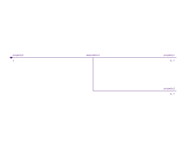
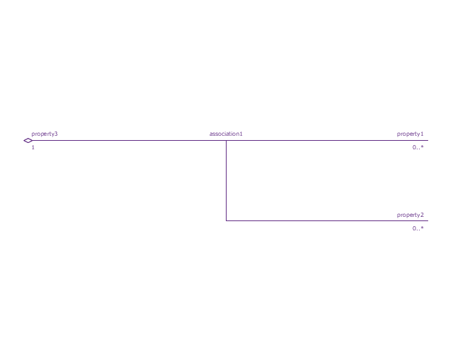
This vector stencils library contains 32 SysML symbols.
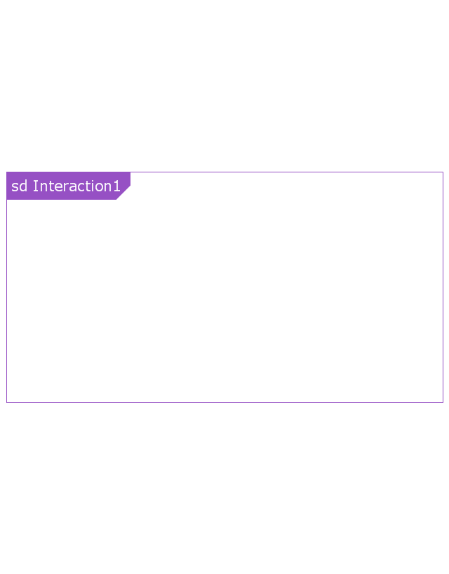
Use it to design your sequence diagrams using ConceptDraw PRO diagramming and vector drawing software.
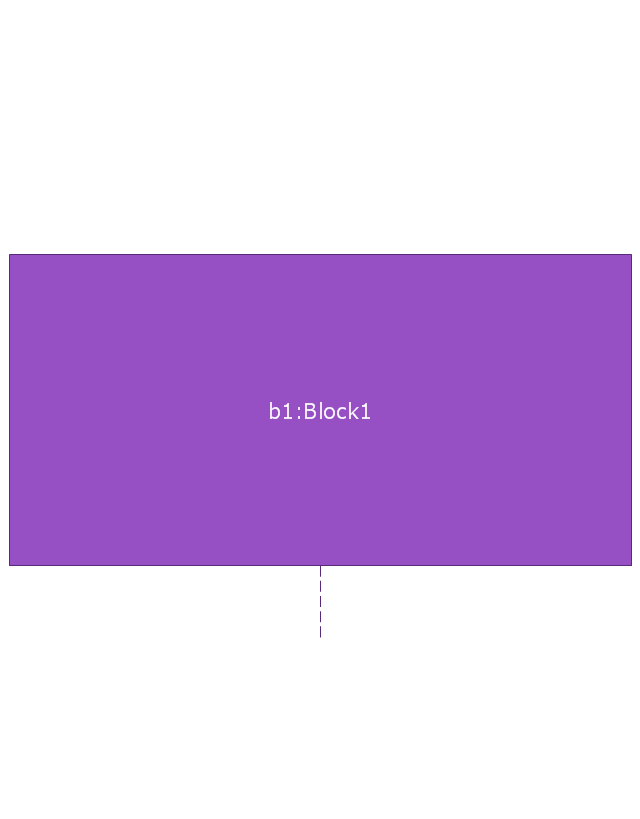
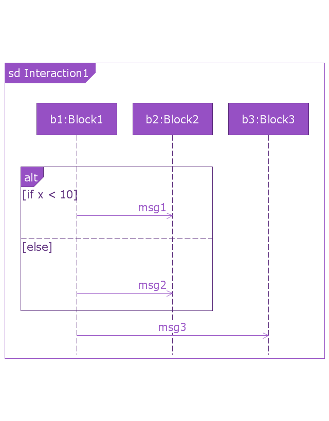
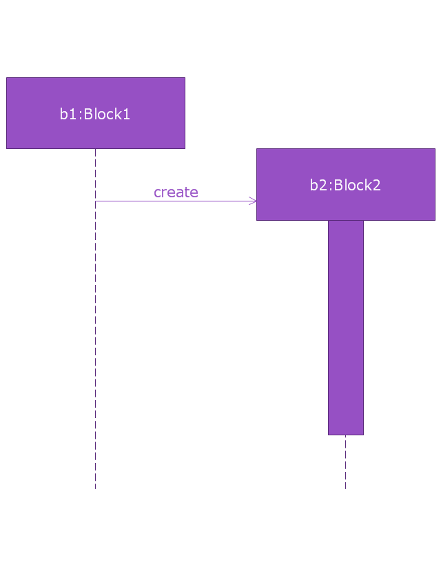
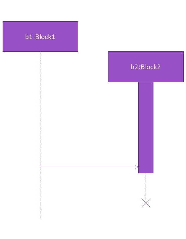
"A sequence diagram shows, as parallel vertical lines (lifelines), different processes or objects that live simultaneously, and, as horizontal arrows, the messages exchanged between them, in the order in which they occur. This allows the specification of simple runtime scenarios in a graphical manner. ...
If the lifeline is that of an object, it demonstrates a role. Leaving the instance name blank can represent anonymous and unnamed instances.
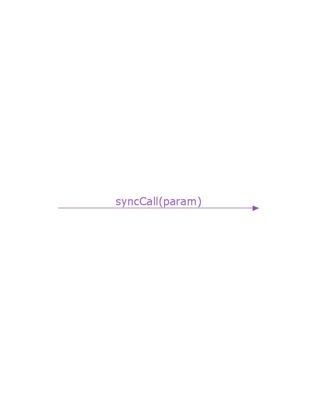
Messages, written with horizontal arrows with the message name written above them, display interaction. Solid arrow heads represent synchronous calls, open arrow heads represent asynchronous messages, and dashed lines represent reply messages. If a caller sends a synchronous message, it must wait until the message is done, such as invoking a subroutine. If a caller sends an asynchronous message, it can continue processing and doesn’t have to wait for a response. Asynchronous calls are present in multithreaded applications and in message-oriented middleware. Activation boxes, or method-call boxes, are opaque rectangles drawn on top of lifelines to represent that processes are being performed in response to the message (ExecutionSpecifications in UML).
Objects calling methods on themselves use messages and add new activation boxes on top of any others to indicate a further level of processing.
When an object is destroyed (removed from memory), an X is drawn on top of the lifeline, and the dashed line ceases to be drawn below it (this is not the case in the first example though). It should be the result of a message, either from the object itself, or another.
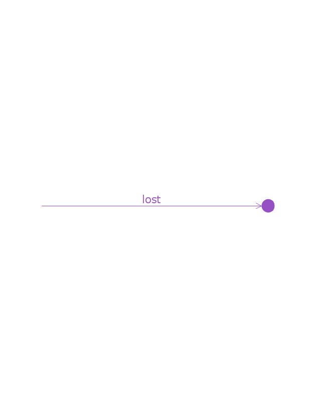
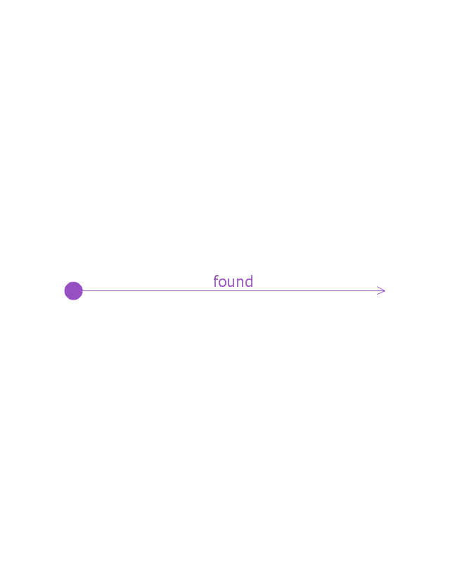
A message sent from outside the diagram can be represented by a message originating from a filled-in circle (found message in UML) or from a border of the sequence diagram (gate in UML)." [Sequence diagram. Wikipedia]
The vector stencils library "Sequence diagram" is included in the SysML solution from the Software Development area of ConceptDraw Solution Park.
Use it to design your sequence diagrams using ConceptDraw PRO diagramming and vector drawing software.
"A sequence diagram shows, as parallel vertical lines (lifelines), different processes or objects that live simultaneously, and, as horizontal arrows, the messages exchanged between them, in the order in which they occur. This allows the specification of simple runtime scenarios in a graphical manner. ...
If the lifeline is that of an object, it demonstrates a role. Leaving the instance name blank can represent anonymous and unnamed instances.
Messages, written with horizontal arrows with the message name written above them, display interaction. Solid arrow heads represent synchronous calls, open arrow heads represent asynchronous messages, and dashed lines represent reply messages. If a caller sends a synchronous message, it must wait until the message is done, such as invoking a subroutine. If a caller sends an asynchronous message, it can continue processing and doesn’t have to wait for a response. Asynchronous calls are present in multithreaded applications and in message-oriented middleware. Activation boxes, or method-call boxes, are opaque rectangles drawn on top of lifelines to represent that processes are being performed in response to the message (ExecutionSpecifications in UML).
Objects calling methods on themselves use messages and add new activation boxes on top of any others to indicate a further level of processing.
When an object is destroyed (removed from memory), an X is drawn on top of the lifeline, and the dashed line ceases to be drawn below it (this is not the case in the first example though). It should be the result of a message, either from the object itself, or another.
A message sent from outside the diagram can be represented by a message originating from a filled-in circle (found message in UML) or from a border of the sequence diagram (gate in UML)." [Sequence diagram. Wikipedia]
The vector stencils library "Sequence diagram" is included in the SysML solution from the Software Development area of ConceptDraw Solution Park.
Sequence diagram
Lifeline
Execution specification

Execution specification 2

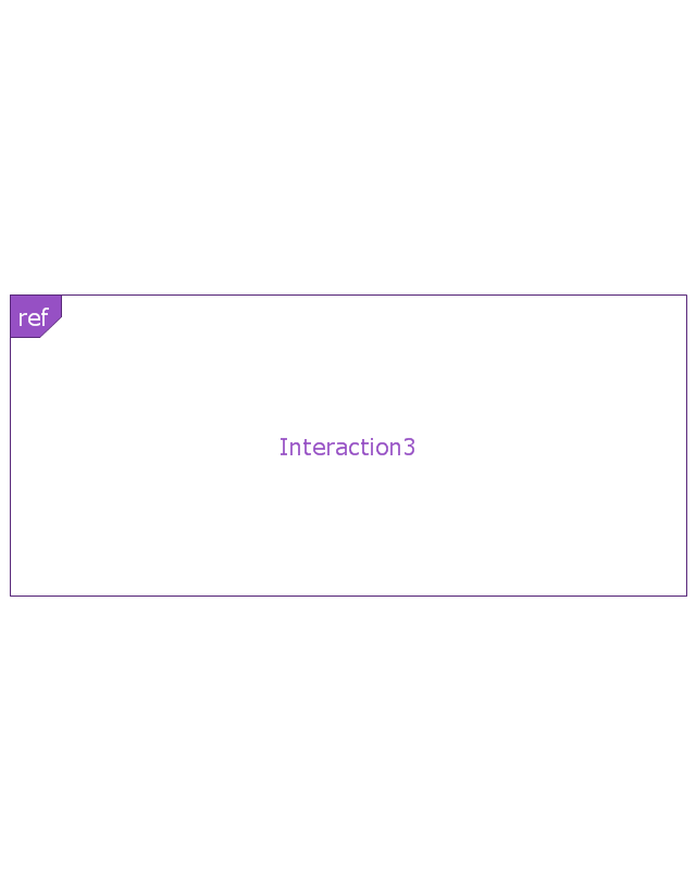
Interaction use
Combined fragment
Combined fragment - Weak sequencing

Combined fragment - Alternatives
Combined fragment - Option

Combined fragment - Break
Combined fragment - Parallel

Combined fragment - Strict sequencing

Combined fragment - Loop
Combined fragment - Critical region
Combined fragment - Negative
Combined fragment - Assertion

Combined fragment - Ignore
Combined fragment - Consider
State invariant / Continuations
Coregion

Creation event
Destruction event
Duration constraint
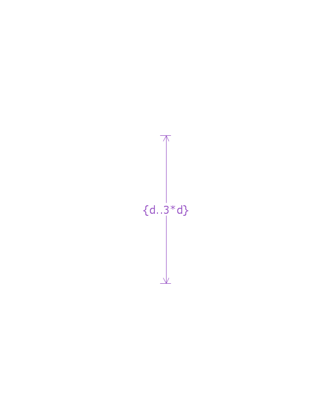
Duration observation
Time constraint

Time observation

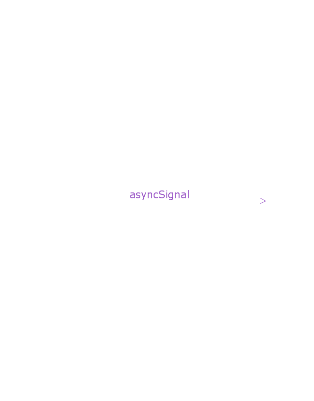
Message, asynchronous signal
Message, synchronous call
Reply message

Lost message
Found message
General ordering

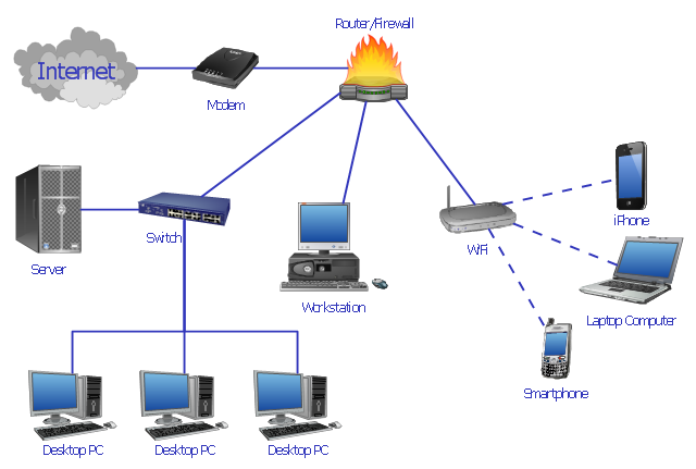
"Network planning and design is an iterative process, encompassing topological design, network-synthesis, and network-realization, and is aimed at ensuring that a new telecommunications network or service meets the needs of the subscriber and operator. Network planning process involves three main steps: 1) Topological design: This stage involves determining where to place the components and how to connect them. 2) Network-synthesis: This stage involves determining the size of the components used, subject to performance criteria such as the Grade of Service (GoS). 3) Network realization: This stage involves determining how to meet capacity requirements, and ensure reliability within the network." [Network planning and design. Wikipedia]
This computer network system design diagram example was created using the ConceptDraw PRO diagramming and vector drawing software extended with the Computer and Networks solution from the Computer and Networks area of ConceptDraw Solution Park.
This computer network system design diagram example was created using the ConceptDraw PRO diagramming and vector drawing software extended with the Computer and Networks solution from the Computer and Networks area of ConceptDraw Solution Park.
Network system design
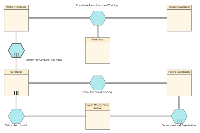
"Franchising is the practice of using another firm's successful business model. ... For the franchisor, the franchise is an alternative to building 'chain stores' to distribute goods that avoids the investments and liability of a chain. The franchisor's success depends on the success of the franchisees. The franchisee is said to have a greater incentive than a direct employee because he or she has a direct stake in the business.
Essentially, and in terms of distribution, the franchisor is a supplier who allows an operator, or a franchisee, to use the supplier's trademark and distribute the supplier's goods. In return, the operator pays the supplier a fee." [Franchising. Wikipedia]
The BPMN 2.0 (Business Process Model and Notation) conversation diagram example "Franchisee recruitment and training" was created using the ConceptDraw PRO diagramming and vector drawing software extended with the Business Process Diagram solution from the Business Processes area of ConceptDraw Solution Park.
Conversation BPMN 2.0 diagram
Interactive Voice Response System

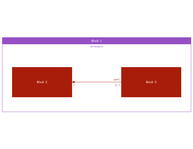
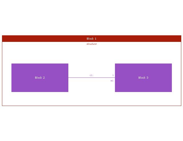
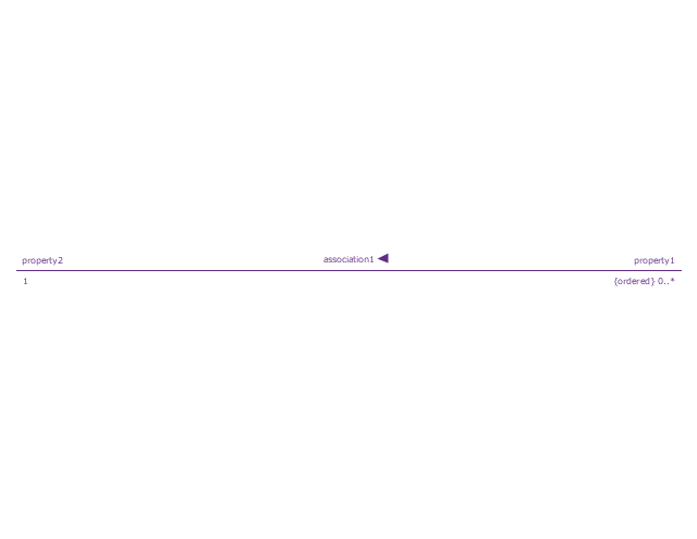
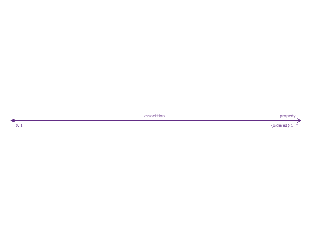
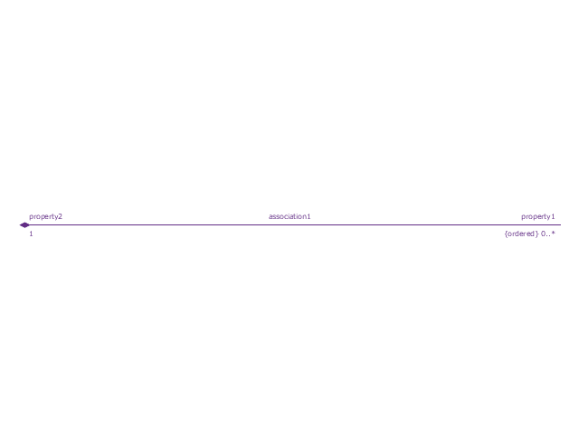
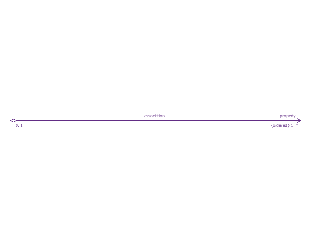
This vector stencils library contains 54 BDD symbols.
Use it to design your block definition diagrams using ConceptDraw PRO diagramming and vector drawing software.
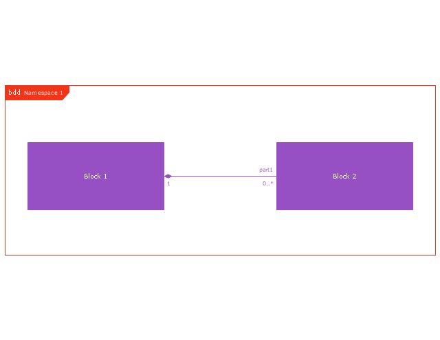
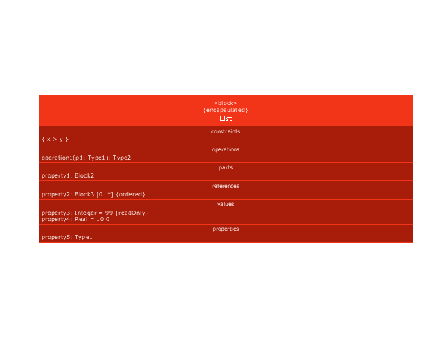
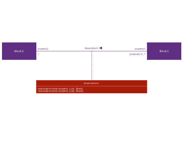
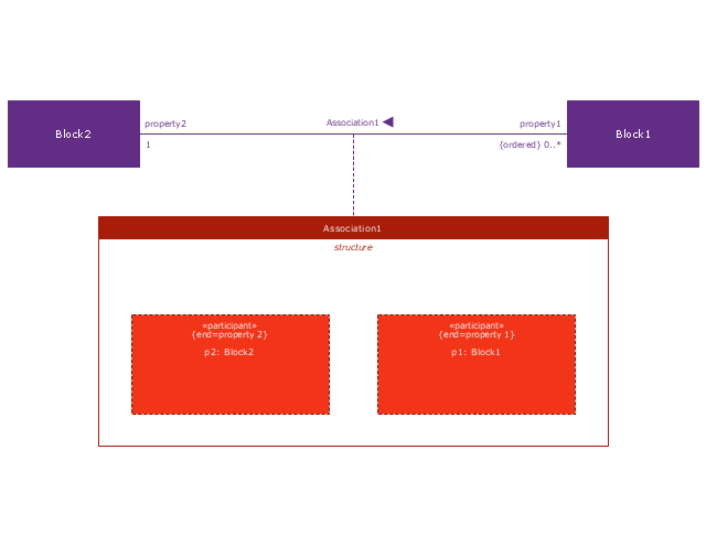
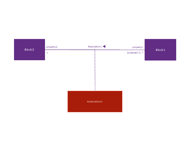
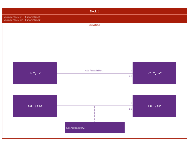
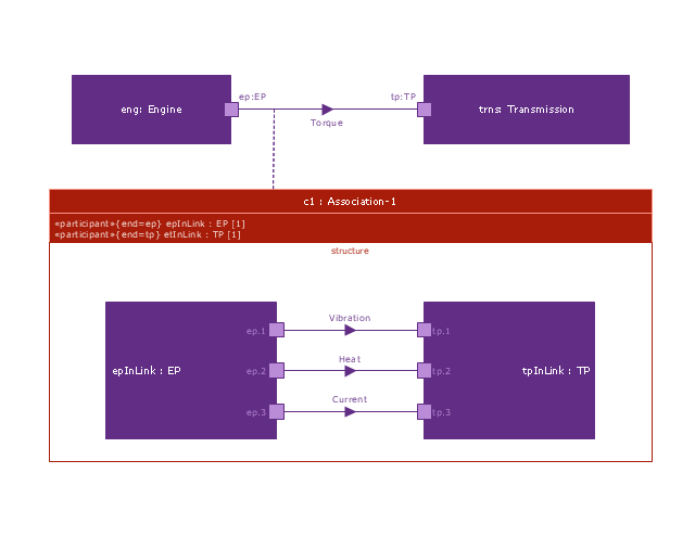
"Block Definition Diagram
A block definition diagram is based on the UML class diagram, with restrictions and extensions as defined by SysML. ...
Block and ValueType Definitions
A SysML Block defines a collection of features to describe a system or other element of interest. A SysML ValueType
defines values that may be used within a model. SysML blocks are based on UML classes, as extended by UML composite structures. SysML value types are based on UML data types. Diagram extensions for SysML blocks and value types are described by other subheadings of this sub clause." [www.omg.org/ spec/ SysML/ 1.3/ PDF]
The vector stencils library "Block definition diagram" is included in the SysML solution from the Software Development area of ConceptDraw Solution Park.
Use it to design your block definition diagrams using ConceptDraw PRO diagramming and vector drawing software.
"Block Definition Diagram
A block definition diagram is based on the UML class diagram, with restrictions and extensions as defined by SysML. ...
Block and ValueType Definitions
A SysML Block defines a collection of features to describe a system or other element of interest. A SysML ValueType
defines values that may be used within a model. SysML blocks are based on UML classes, as extended by UML composite structures. SysML value types are based on UML data types. Diagram extensions for SysML blocks and value types are described by other subheadings of this sub clause." [www.omg.org/ spec/ SysML/ 1.3/ PDF]
The vector stencils library "Block definition diagram" is included in the SysML solution from the Software Development area of ConceptDraw Solution Park.
Block definition diagram
Block
Actor
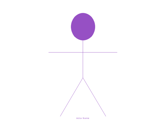
Actor 2

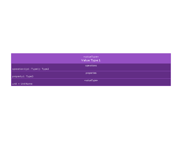
Value type
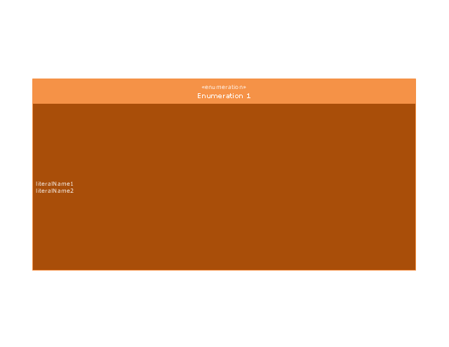
Enumeration
Abstract definition

Abstract definition 2
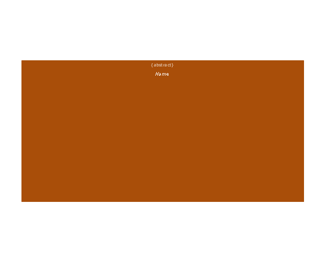
Abstract definition 3
Stereotype property compartment
Namespace compartment
Structure compartment
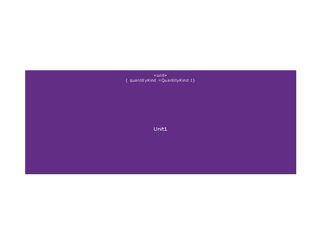
Unit
Unit 2
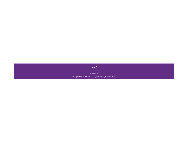
Quantity kind

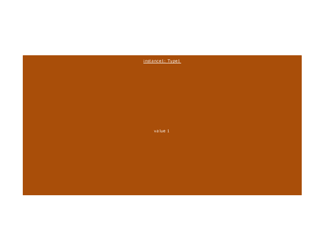
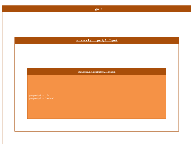
Instance specification
Instance specification 2
Instance specification 3
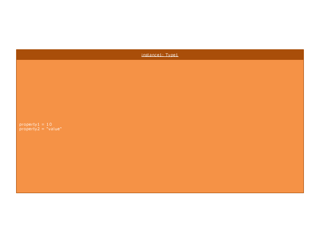
Instance specification 4
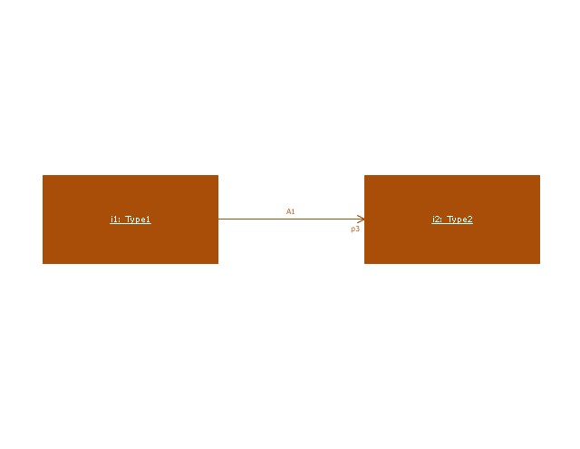
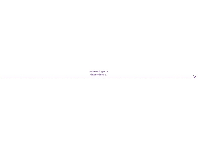
Dependency
Reference association
Reference association 2
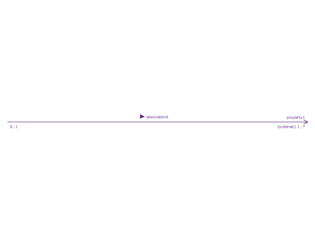
Part association
Part association 2
Shared association
Shared association 2

Multibranch part association
Multibranch shared association
Generalization

Multibranch generalization
Generalization set, disjoint
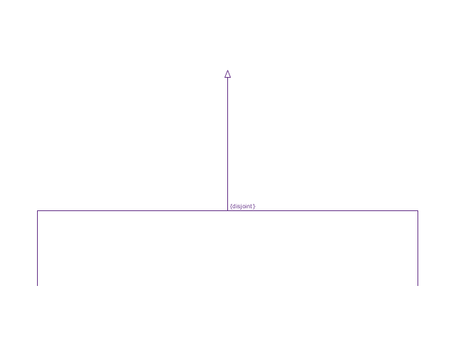
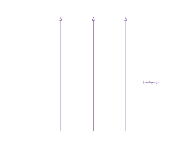
Generalization set, overlapping
Block namespace containment
Participant property
Participant property 2
Participant property 3
Connector property
Conjugated ports
Conjugated ports 2
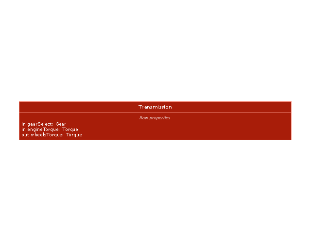
Ports with flow properties
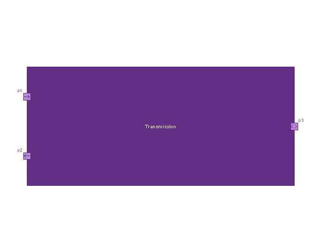
Port (compartment notation)
-vector-stencils-library---block-definition-diagram.png--diagram-flowchart-example.png)
Port (nested)
-vector-stencils-library---block-definition-diagram.png--diagram-flowchart-example.png)
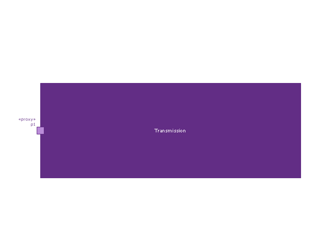
Proxy port
Full port

Flow property
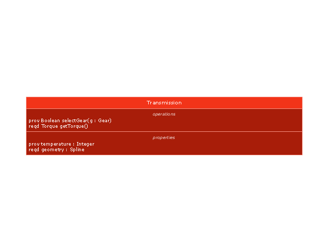
Required and provided features
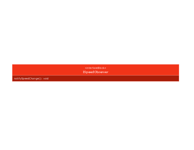
Interface block
Item flow
Item flow 2
Item flow 3
Interface
Required and provided interfaces

Required and provided interfaces 2
Constraint block
The vector stencils library "Workflow diagrams" contains 54 symbol icons of workflow diagrams.
The workflow diagrams represent information flow, automation of business processes, business process re-engineering, accounting, management, and human resources tasks in industry, business, and manufacturing.
Use this library to draw workflow diagrams in the ConceptDraw PRO diagramming and vector drawing software extended with the Workflow Diagrams solution from the Business Processes area of ConceptDraw Solution Park.
www.conceptdraw.com/ solution-park/ business-process-workflow-diagrams
Accounting

Accounts Payable

Accounts Receivable

Bank

Board of Directors

Copy Center

Customer Service

Distribution
Finance

Information Systems

International Division

International Marketing

International Sales

Inventory

Legal Department

Mailroom 2

Mailroom 1

Management
Manufacturing

Marketing

Motor Pool

Packaging

Payroll
Person 1

Person 2

Personnel/ Staff
Publications

Purchasing

Quality Assurance

Exchange

Reception

Research and Development

Sale contract

Shipping

Suppliers

Telecommunications

Treasurer

Warehouse
Lorry

Quality

Production

Box

Boxes

Open box

Payment

Receiving

Sales

Phone

Operator 1

Online booking

Operator 2

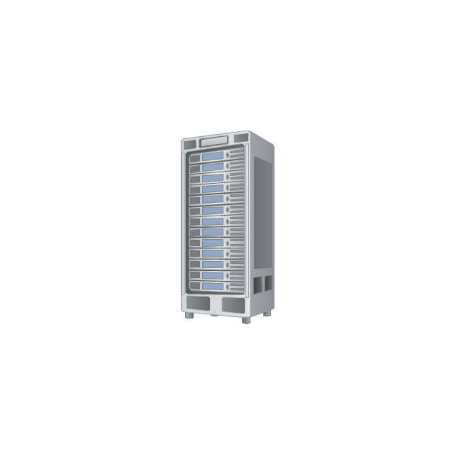
Server
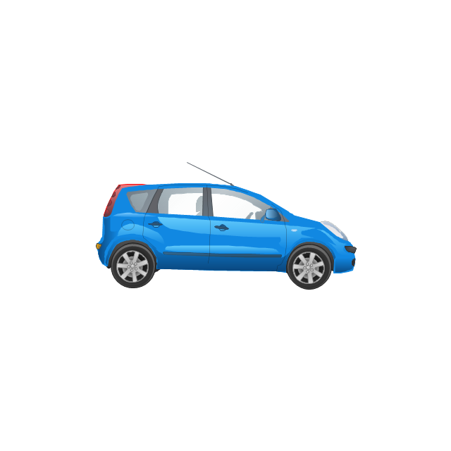
Car
Mini truck

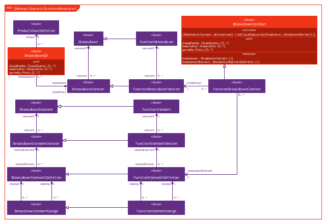
This example was drawn on the base of figure 1 on the webpage "Template: OASIS:FunctionalBreakdownStructure" from the OASIS website.
"The FunctionalBreakdownStructure template describes how to represent a relationship between a FunctionalElementDefinition and another FunctionalElementDefinition that is a constituent.
The SysML Block Definition diagram in Figure 1 shows how a functional breakdown is represented in the PLCS PSM."
[docs.oasis-open.org/ plcs/ plcslib/ v1.0/ csprd01/ data/ contexts/ OASIS/ templates/ FunctionalBreakdownStructure/ template.html]
"A block definition diagram is based on the UML class diagram, with restrictions and extensions as defined by SysML." [omg.org/ spec/ SysML/ 1.3/ PDF]
The example "SysML block definition diagram - Function Breakdown model" was drawn using the ConceptDraw PRO diagramming and vector drawing software extended with the SysML solution from the Software Development area of ConceptDraw Solution Park.
Example of SysML BDD
- And Operator
- Operator hierarchy - Natural hierarchy rearranged | Access and ...
- Data Flow Diagram Model
- Process Flowchart | How to Create Flowcharts for an Accounting ...
- Software Diagram Examples and Templates | Er Diagram Prepaid ...
- EPC diagrams - Vector stencils library | EPC diagrams - Vector ...
- Operator hierarchy - Natural hierarchy rearranged | Astronomy ...
- IVR services diagram | IVR balance recharge diagram | IVR mobile ...
- IVR | IVR mobile operator diagram | PM Response | Diagram Of ...
- Interactive Voice Response Diagrams | Service Operator Er Diagram ...
- IVR mobile operator diagram
- Interactive Voice Response Diagrams | Telephone Operator Flow ...
- Login and registration processing - EPC diagram | Business process ...
- Interactive Voice Response Diagrams | IVR time auto-attendant ...
- Computer network system design diagram | How to Draw a ...
- Event-driven process chain (EPC) diagram | Process Flowchart ...
- Use the Best FlowChart Tool for the Job | Affinity diagram - Checkout ...
- Franchisee recruitment and training - Conversation BPMN 2.0 diagram
- Computer network system design diagram
- Design elements - Aircraft | Fishbone Diagram | Design elements ...