How To use House Electrical Plan Software


Wiring Diagrams with ConceptDraw DIAGRAM

Electrical Symbols, Electrical Diagram Symbols

Electrical Symbols — Terminals and Connectors

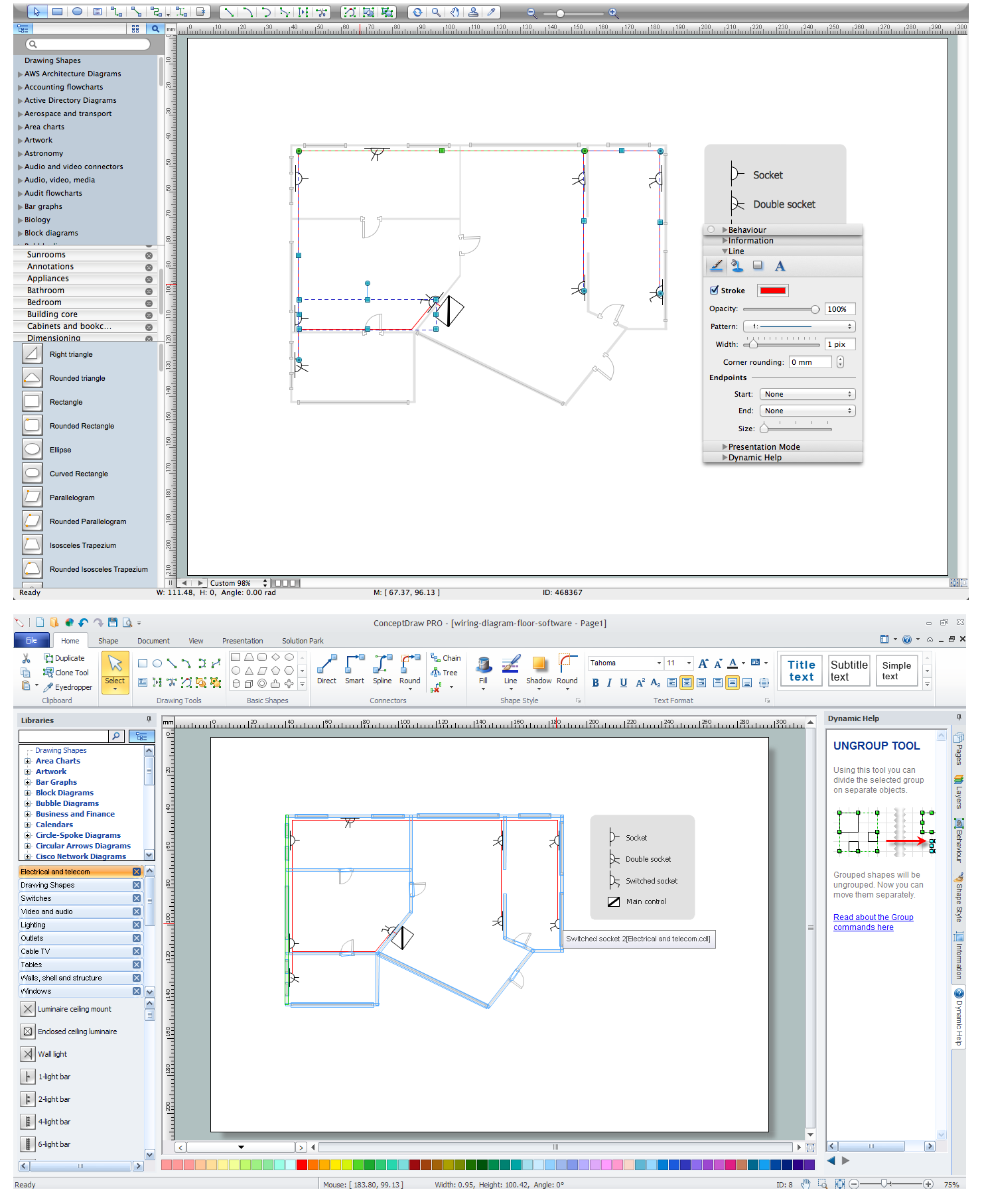
 Electric and Telecom Plans
The Electric and Telecom Plans solution providing the electric and telecom-related stencils, floor plan electrical symbols and pre-made examples is useful for electricians, interior designers, telecommunications managers, builders and other technicians when creating the electric visual plans and telecom drawings, home electrical plan, residential electric plan, telecom wireless plan, electrical floor plans whether as a part of the building plans or the independent ones.
 Electrical Engineering
This solution extends ConceptDraw DIAGRAM.9.5 (or later) with electrical engineering samples, electrical schematic symbols, electrical diagram symbols, templates and libraries of design elements, to help you design electrical schematics, digital and analog
Wiring Diagram Floor Software
Electrical Drawing Software and Electrical Symbols

Electrical Symbols — Inductors

Electrical Symbols — Power Sources

- Basic Electrical Video Tamil Download
- House Wiring In Hindi Videos Download
- House Wiring Pdf In Hindi
- Basic House Wiring Manual Electrical Video Download
- How To use House Electrical Plan Software | Home Electrical Plan ...
- How to Create a Hook Up Diagram | ConceptDraw Arrows10 ...
- Industrial Wiring Pdf Hindi
- How To Draw Building Plans | Electrical Basics Pdf In Tamil
- Electrical Symbols, Electrical Diagram Symbols | Metropolitan area ...
- Electrical Symbols, Electrical Diagram Symbols | Wiring Diagrams ...