Flowchart Maker
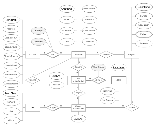
"In software engineering, an entity–relationship model (ER model) is a data model for describing a database in an abstract way.Chen's notation for entity–relationship modeling uses rectangles to represent entity sets, and diamonds to represent relationships appropriate for first-class objects: they can have attributes and relationships of their own. If an entity set participates in a relationship set, they are connected with a line.
Attributes are drawn as ovals and are connected with a line to exactly one entity or relationship set." [Entity–relationship model. Wikipedia]
This sample Chen's ER-diagram illustrates the structure of a typical MMORP game.
"Massively multiplayer online role-playing game (MMORPG) mixes the genres of role-playing video games and Massively multiplayer online games, possibly in the form of web browser-based games, in which a very large number of players interact with one another within a virtual world.
As in all RPGs, players assume the role of a character (often in a fantasy world or science-fiction world) and take control over many of that character's actions. MMORPGs are distinguished from single-player or small multi-player online RPGs by the number of players, and by the game's persistent world (usually hosted by the game's publisher), which continues to exist and evolve while the player is offline and away from the game." [Massively multiplayer online role-playing game. Wikipedia]
This ERD example was redrawn using the ConceptDraw PRO diagramming and vector drawing software from the Wikipedia file: ER Diagram MMORPG.png. [en.wikipedia.org/ wiki/ File:ER_ Diagram_ MMORPG.png]
This file is licensed under the Creative Commons Attribution-Share Alike 3.0 Unported license. [creativecommons.org/ licenses/ by-sa/ 3.0/ deed.en]
This Chen's ERD example is included in the Chen Notation solution from the Software Development area of ConceptDraw Solution Park.
ER-diagram
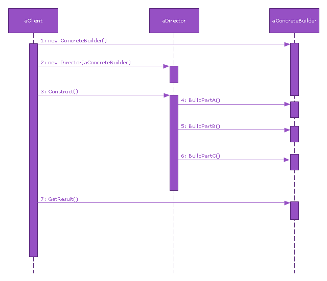
This sequence diagram example was redesigned from the Wikimedia Commons file: Builder design pattern sequence1.png.
"The UML sequence diagram which illustrates the Builder design pattern."
[commons.wikimedia.org/ wiki/ File:Builder_ design_ pattern_ sequence1.png]
"The builder pattern is an object creation software design pattern. Unlike the abstract factory pattern and the factory method pattern whose intention is to enable polymorphism, the intention of the builder pattern is to find a solution to the telescoping constructor anti-pattern. ... The intent of the Builder design pattern is to separate the construction of a complex object from its representation. By doing so the same construction process can create different representations." [Builder pattern. Wikipedia]
The SysML sequence diagram example "Builder design pattern sequence" was drawn using the ConceptDraw PRO diagramming and vector drawing software extended with the SysML solution from the Software Development area of ConceptDraw Solution Park.
SysML system diagram
Entity Relationship Diagram Symbols

The vector stencils library "HR workflow" contains 60 HR workflow symbols.
Use this HR icon set to draw your HR flowcharts, workflow diagrams and process charts with the ConceptDraw PRO diagramming and vector drawing software.
The HR pictograms library "HR workflow" is included in the HR Flowcharts solution from the Management area of ConceptDraw Solution Park.
Use this HR icon set to draw your HR flowcharts, workflow diagrams and process charts with the ConceptDraw PRO diagramming and vector drawing software.
The HR pictograms library "HR workflow" is included in the HR Flowcharts solution from the Management area of ConceptDraw Solution Park.
Applicant

Award

Bank data

Blog

Business conference

Checklist

Compensation and benefits

Contract of employment

Cost planning and reporting

Credit plan

CV (resume, abstract)
-hr-workflow---vector-stencils-library.png--diagram-flowchart-example.png)
Disciplinary procedures

Employee man

Employee woman

Engage and retain

Family

Flexible spending account

Functions

Geolocation

Health plan

Hiring

Human resource

Human resources

Illness

Insurance

Job descriptions

Job offer

Job pricing

Job search

Leave

Manager

Meeting

Negotiation

Onboarding

Online application

Organizational assignment

Outsourcing

Overtime

Payment

Pensioner

Person specification

Personal data (badge icon)
-hr-workflow---vector-stencils-library.png--diagram-flowchart-example.png)
Personal profile

Personnel / staff / employees

Position / occupation

Reception

Recruitment

Remuneration (payment, salary, wage)
-hr-workflow---vector-stencils-library.png--diagram-flowchart-example.png)
Resume

Schedule

Social networks

Survey

Tax data

Team

Time evaluation

Time sheet

Time statement

Training

Vacancy

Vacant post

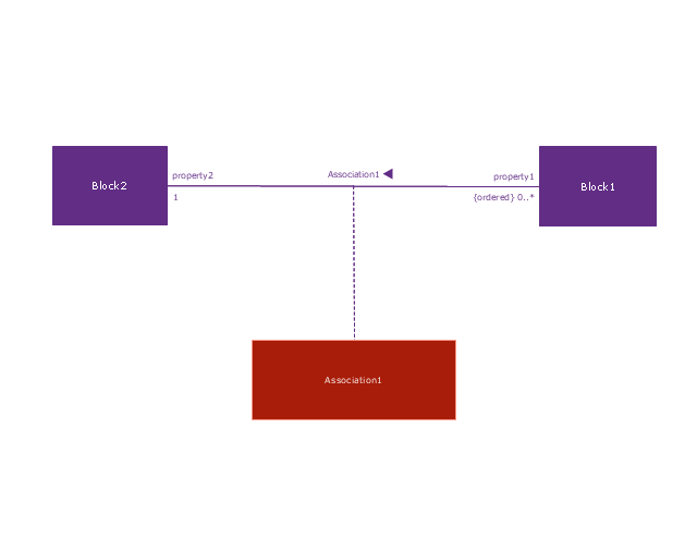
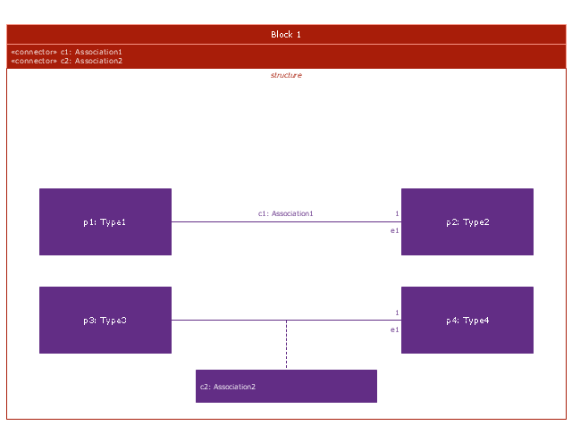
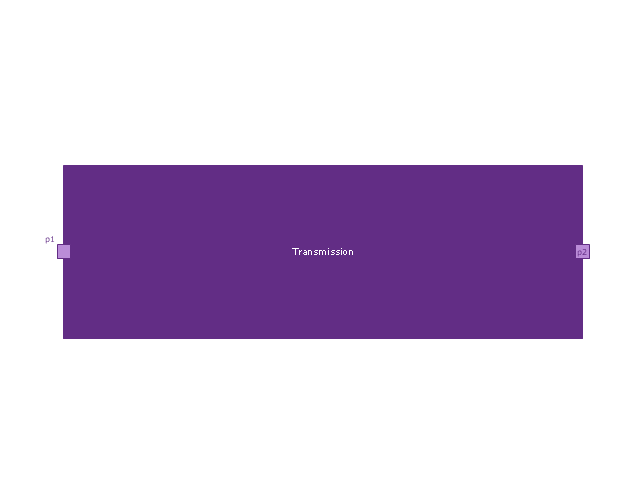
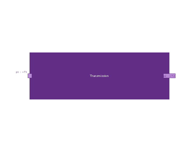
This vector stencils library contains 54 BDD symbols.
Use it to design your block definition diagrams using ConceptDraw PRO diagramming and vector drawing software.
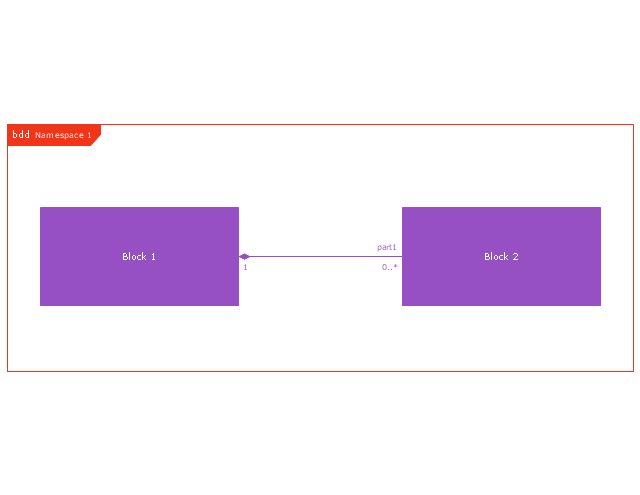
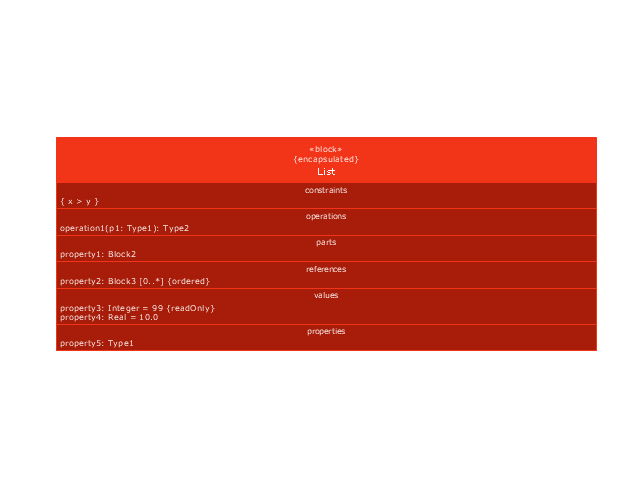
"Block Definition Diagram
A block definition diagram is based on the UML class diagram, with restrictions and extensions as defined by SysML. ...
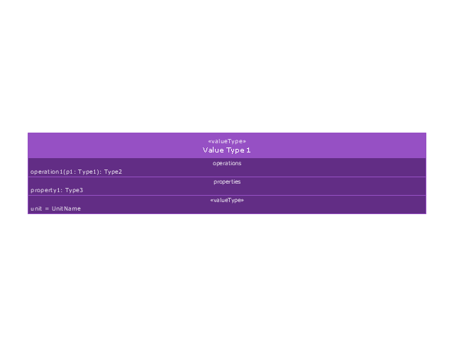
Block and ValueType Definitions
A SysML Block defines a collection of features to describe a system or other element of interest. A SysML ValueType
defines values that may be used within a model. SysML blocks are based on UML classes, as extended by UML composite structures. SysML value types are based on UML data types. Diagram extensions for SysML blocks and value types are described by other subheadings of this sub clause." [www.omg.org/ spec/ SysML/ 1.3/ PDF]
The vector stencils library "Block definition diagram" is included in the SysML solution from the Software Development area of ConceptDraw Solution Park.
Use it to design your block definition diagrams using ConceptDraw PRO diagramming and vector drawing software.
"Block Definition Diagram
A block definition diagram is based on the UML class diagram, with restrictions and extensions as defined by SysML. ...
Block and ValueType Definitions
A SysML Block defines a collection of features to describe a system or other element of interest. A SysML ValueType
defines values that may be used within a model. SysML blocks are based on UML classes, as extended by UML composite structures. SysML value types are based on UML data types. Diagram extensions for SysML blocks and value types are described by other subheadings of this sub clause." [www.omg.org/ spec/ SysML/ 1.3/ PDF]
The vector stencils library "Block definition diagram" is included in the SysML solution from the Software Development area of ConceptDraw Solution Park.
Block definition diagram
Block
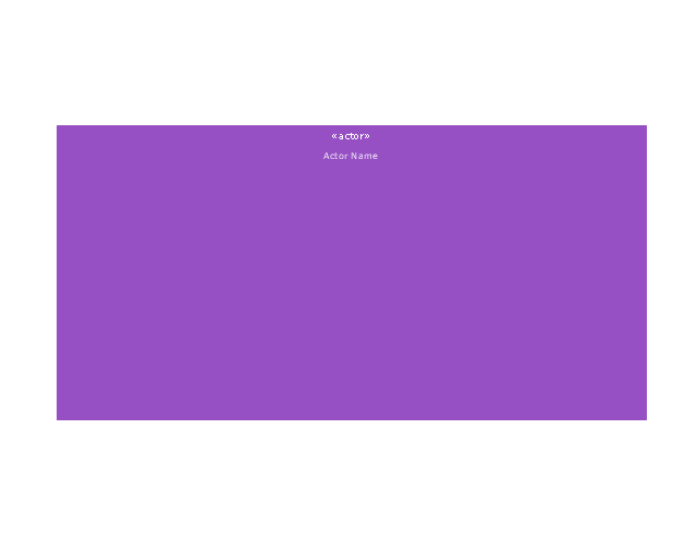
Actor
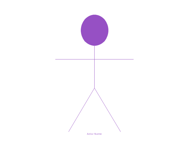
Actor 2
Value type
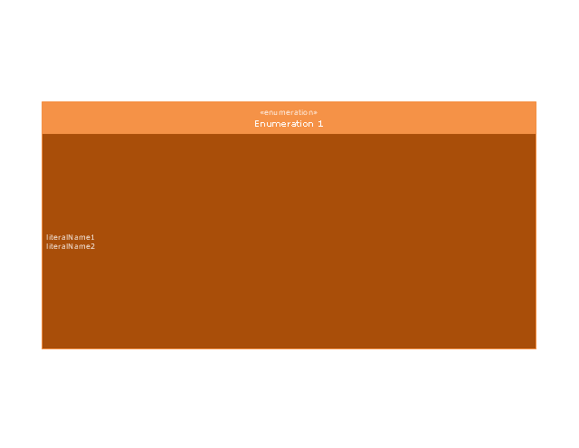
Enumeration
Abstract definition
Abstract definition 2
Abstract definition 3
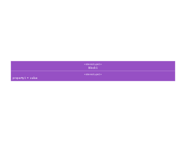
Stereotype property compartment
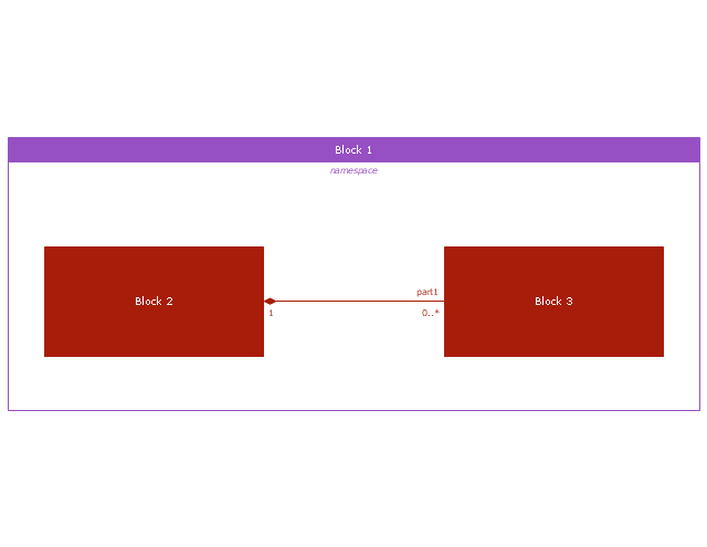
Namespace compartment
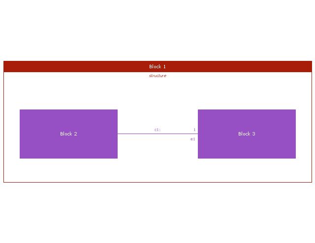
Structure compartment
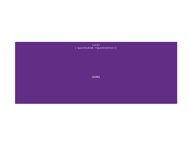
Unit
Unit 2
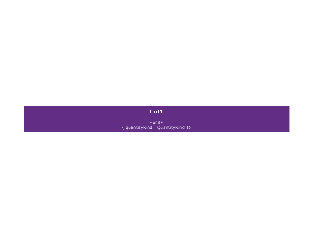
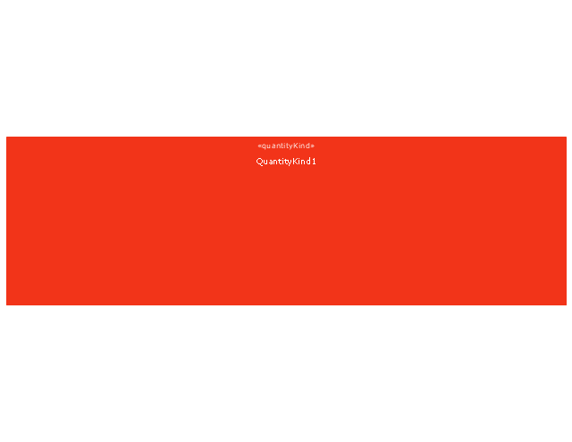
Quantity kind
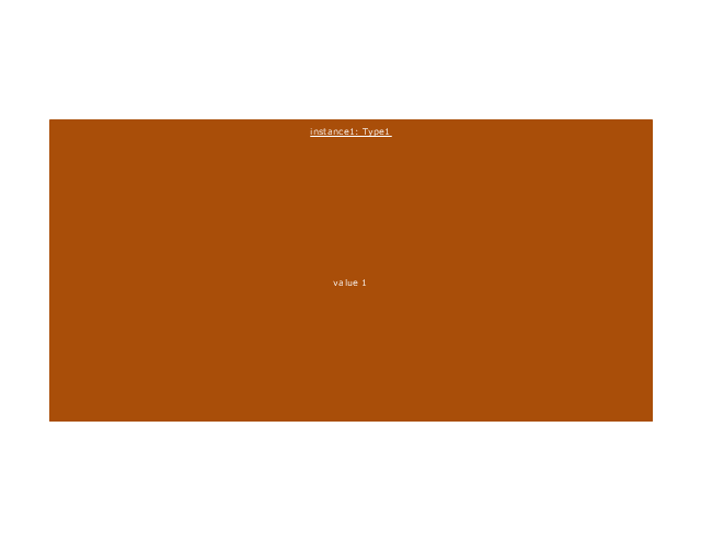
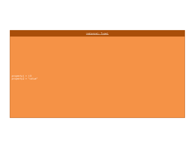
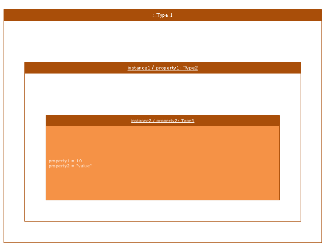
Instance specification
Instance specification 2
Instance specification 3
Instance specification 4
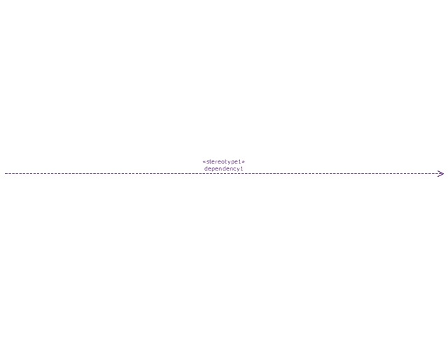
Dependency
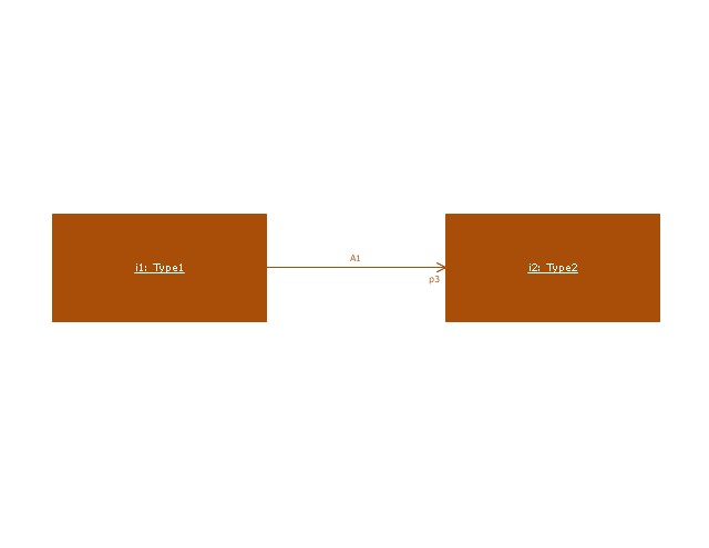
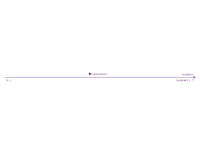
Reference association
Reference association 2
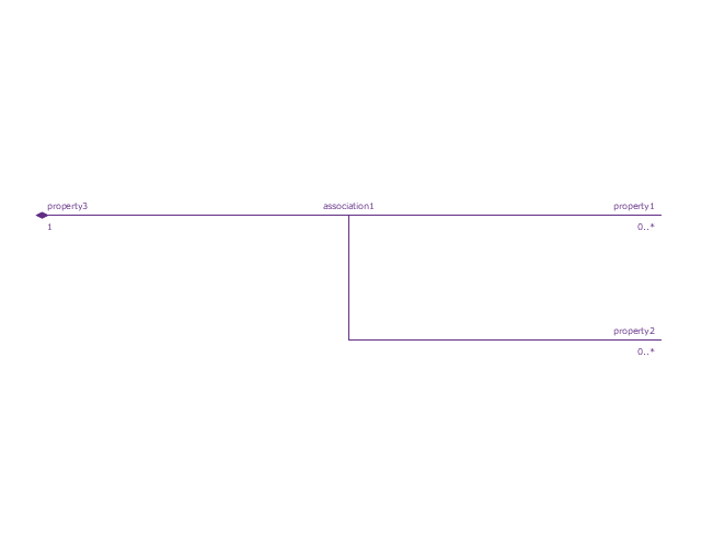
Part association
Part association 2
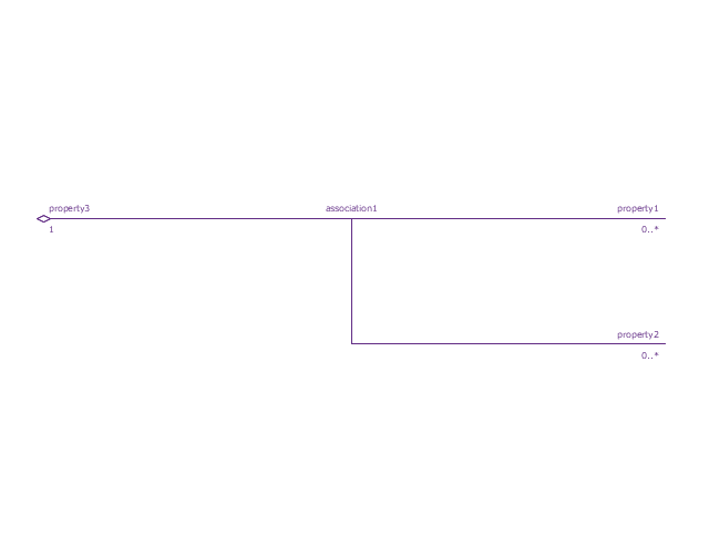
Shared association
Shared association 2

Multibranch part association
Multibranch shared association
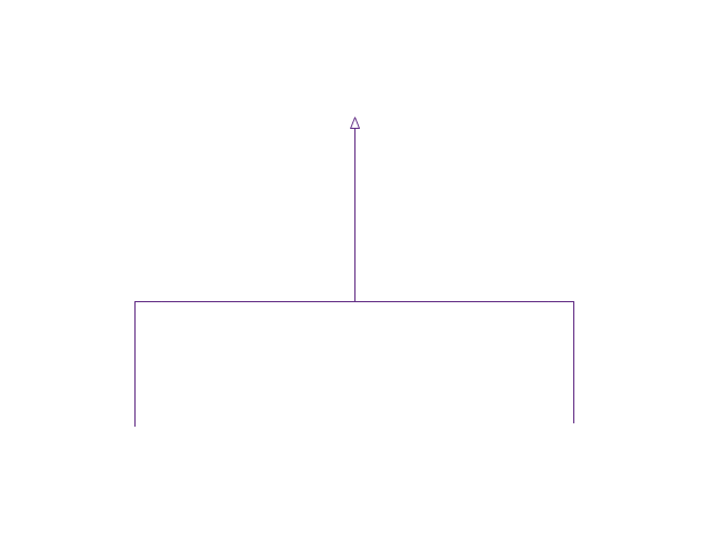
Generalization

Multibranch generalization
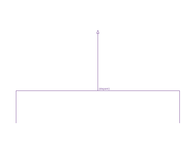
Generalization set, disjoint
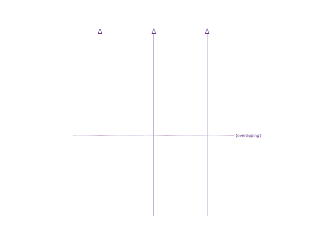
Generalization set, overlapping
Block namespace containment
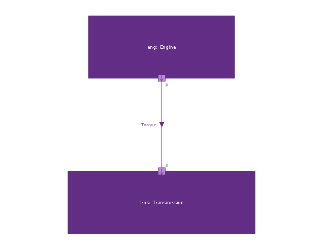
Participant property
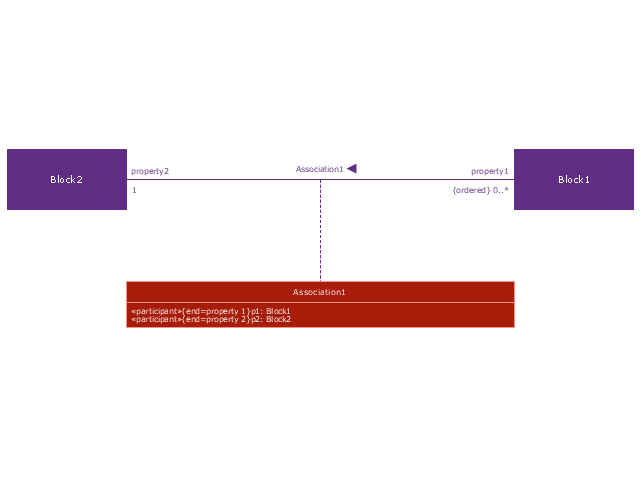
Participant property 2
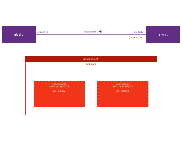
Participant property 3
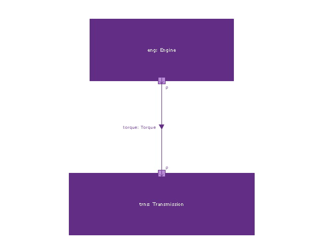
Connector property
Conjugated ports
Conjugated ports 2
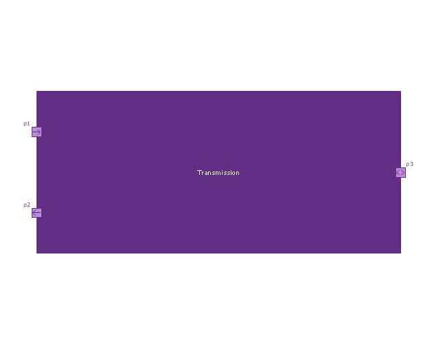
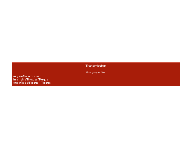
Ports with flow properties
Port (compartment notation)
-vector-stencils-library---block-definition-diagram.png--diagram-flowchart-example.png)
Port (nested)
-vector-stencils-library---block-definition-diagram.png--diagram-flowchart-example.png)
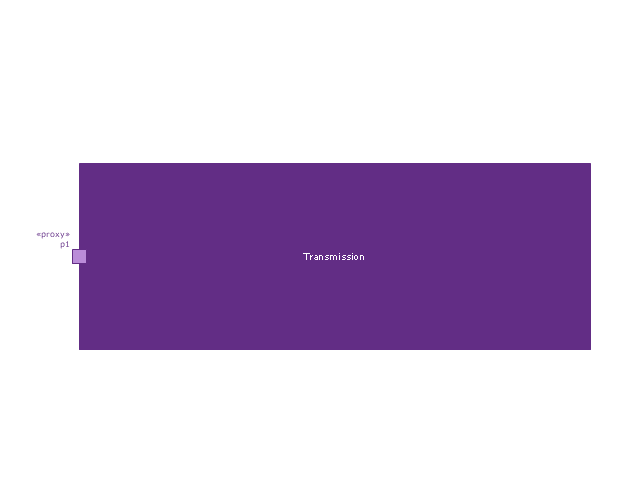
Proxy port
Full port

Flow property
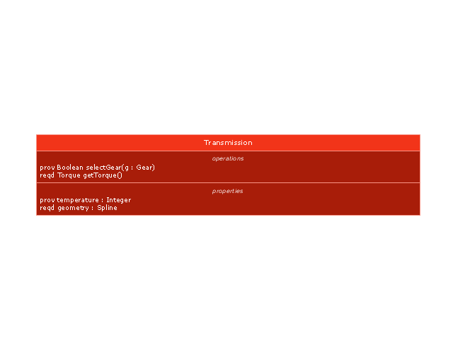
Required and provided features
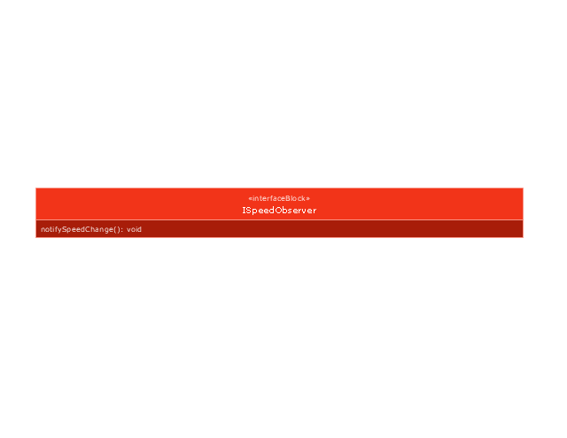
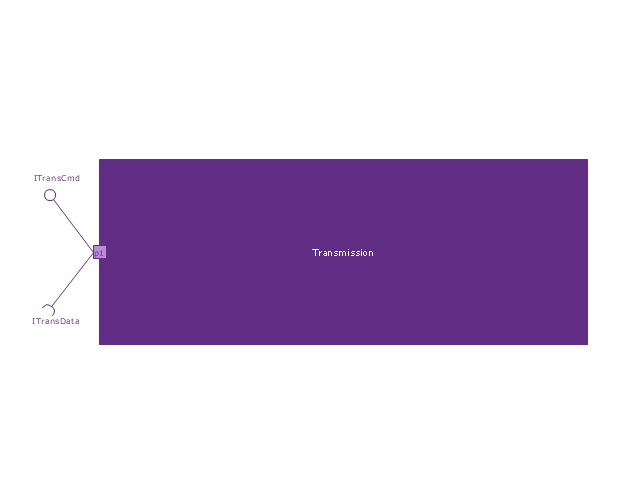
Interface block
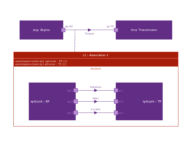
Item flow
Item flow 2
Item flow 3
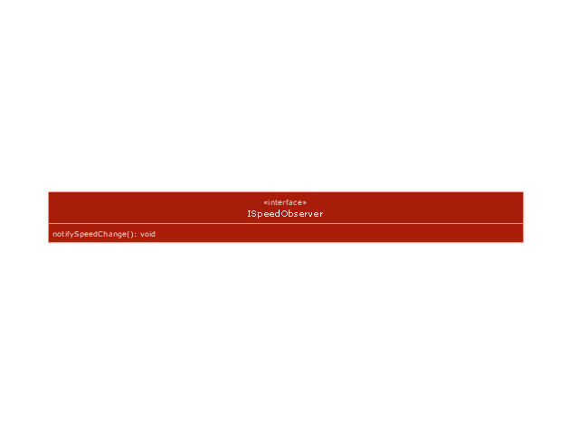
Interface
Required and provided interfaces

Required and provided interfaces 2
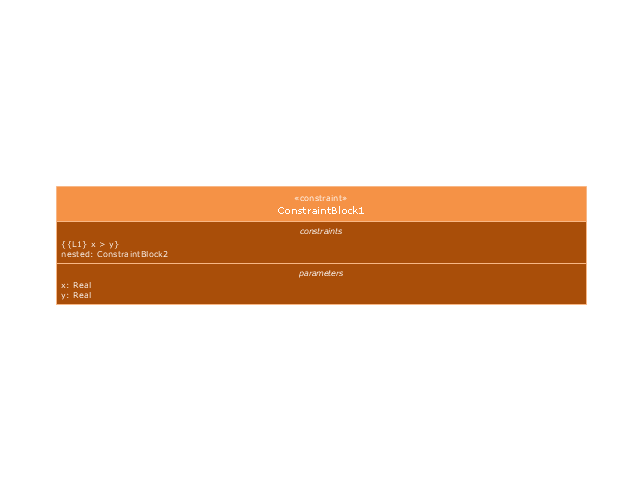
Constraint block
This vector stencils library contains 54 BDD symbols.
Use it to design your block definition diagrams using ConceptDraw PRO diagramming and vector drawing software.
"Block Definition Diagram
A block definition diagram is based on the UML class diagram, with restrictions and extensions as defined by SysML. ...
Block and ValueType Definitions
A SysML Block defines a collection of features to describe a system or other element of interest. A SysML ValueType
defines values that may be used within a model. SysML blocks are based on UML classes, as extended by UML composite structures. SysML value types are based on UML data types. Diagram extensions for SysML blocks and value types are described by other subheadings of this sub clause." [www.omg.org/ spec/ SysML/ 1.3/ PDF]
The vector stencils library "Block definition diagram" is included in the SysML solution from the Software Development area of ConceptDraw Solution Park.
Block definition diagram
Block
Actor
Actor 2
Value type
Enumeration
Abstract definition
Abstract definition 2
Abstract definition 3
Stereotype property compartment
Namespace compartment
Structure compartment
Unit
Unit 2
Quantity kind
Instance specification
Instance specification 2
Instance specification 3
Instance specification 4
Dependency
Reference association
Reference association 2
Part association
Part association 2
Shared association
Shared association 2
Multibranch part association
Multibranch shared association
Generalization
Multibranch generalization
Generalization set, disjoint
Generalization set, overlapping
Block namespace containment
Participant property
Participant property 2
Participant property 3
Connector property
Conjugated ports
Conjugated ports 2
Ports with flow properties
Port (compartment notation)
Port (nested)
Proxy port
Full port
Flow property
Required and provided features
Interface block
Item flow
Item flow 2
Item flow 3
Interface
Required and provided interfaces
Required and provided interfaces 2
Constraint block
SIPOC Diagram

How To Create Onion Diagram
Draw Fishbone Diagram on MAC Software
