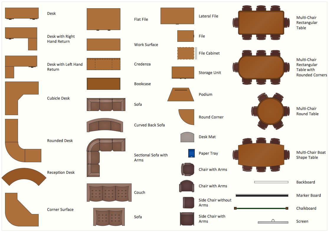
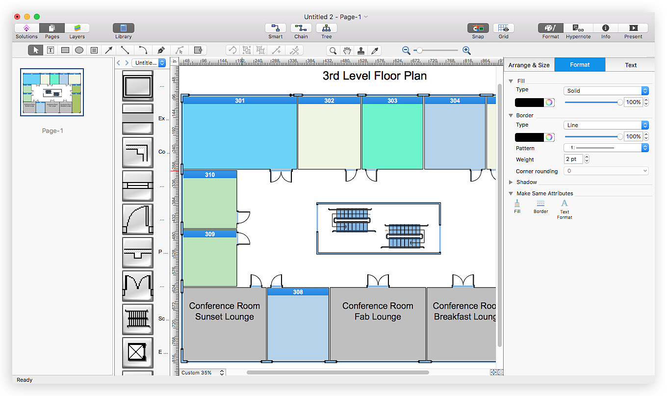
Interior Design Office Layout Plan Design Element
Lucky interior design is an integral part of succesful work at office. The important challenge in office design planning is to find a balance between two main office activities: concentration and communication. Primarily you need to determine with a type of office space, this can be an open space or separate rooms. The first type is more suitable for communication and rapid interaction. That's why open offices and combined spaces are modern types of work space and often used, especially for private offices. Traditional office basically represents separate rooms arranged along the corridor. It is applied for the companies with small number of people or for enterprises divided on separate departments, and is practically inapplicable for teamwork. ConceptDraw PRO diagramming and vector drawing software extended with Office Layout Plans solution offers a lot of vector stencils libraries with design elements of office furniture and equipment for effective office interior design and office space planning, for easy creation Office Floor Plans and Office Layout Plans. Use ConceptDraw PRO to visualize process flowcharts, network architecture and program workflows like Visio for Mac and even more. The software can be used with different fields like business, engineering and construction, etc.
HelpDesk
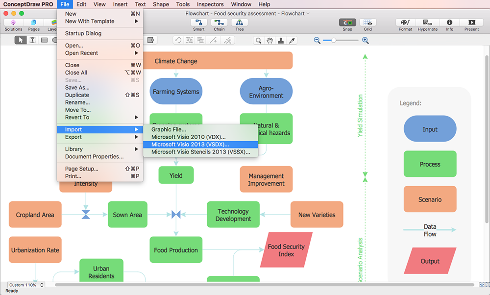
How to Open MS Visio® 2013/2016 Files on a Mac®
Powerful business graphics and diagramming tools are the norm and not the exception for today’s businesses. For years the de facto standard file format for business has been Microsoft Visio™. Many people involved in visual communication need software tools that will read and write using the Visio file format. With the introduction of Visio 2013 Microsoft has changed the native file format used in earlier versions of Microsoft Visio. ConceptDraw PRO v10 file import and export works round-trip with the new Visio VSDX file format.HelpDesk
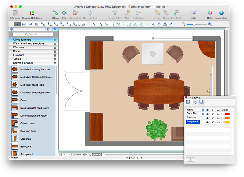
How to Draw a Floor Plan for Your Office
Designing the right office space is is an essential factor of business productivity. An office floor plan should reflect the needs of both employees and customers. ConceptDraw PRO allows you to draw the Floor Plan for your office using a special office equipment library as well as set of?special objects that?displays the?sizes, corners, squares and other floor plan details.HelpDesk
ConceptDraw Office for Apple macOS Installation Definition
With the introduction of version?3, ConceptDraw?Office has been redesigned to?better accommodate future developments and solution plugins. ConceptDraw?Office?3 includes ConceptDraw?PRO?10, ConceptDraw?MINDMAP?8, and ConceptDraw?PROJECT?7. The renewed ConceptDraw STORE helps user manage downloads of ConceptDraw products and solutions. The following article provides owners of the previous versions of ConceptDraw products with important information on updating on ConceptDraw Office v3.Office Ideas
ConceptDraw PRO diagramming and vector drawing software offers the Office Layout Plans Solution from the Building Plans Area of ConceptDraw Solution Park with powerful tools to help you depict your construction and design Office Ideas.How To Draw Building Plans
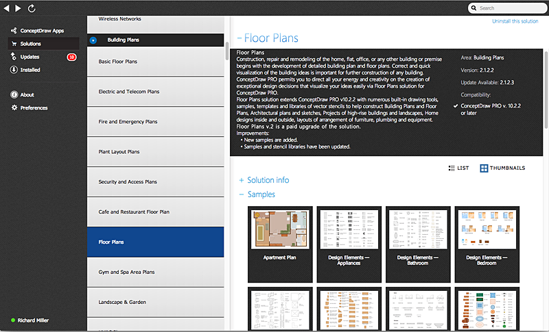
Building Plan is the basis for implementation construction and repair works. Creation of Building Plans is the main purpose of architects and designers. They are required and even obligatory for builders to accurately implement your wishes and ideas during the building, designing or redesigning your home, flat, office, or any other premise. ConceptDraw PRO is a powerful quick building plan software for creating great-looking Office layouts, Home floor plans, Commercial floor plans, Storage building plans, Expo and Shopping mall building plans, School and Training building plans, Cafe or Restaurant plans, Gym and Spa area plans, Sport field plans, House interior designs, Electric and Telecom building plans, Fire and Emergency plans, HVAC plans, Security and Access plans, Plumbing and Piping plans, Plant layouts, etc. Use helpful samples, templates and variety of libraries with numerous building design elements from Floor Plans solution for ConceptDraw PRO software to facilitate design drawing process.
 Office Layout Plans
Office layouts and office plans are a special category of building plans and are often an obligatory requirement for precise and correct construction, design and exploitation office premises and business buildings. Designers and architects strive to make office plans and office floor plans simple and accurate, but at the same time unique, elegant, creative, and even extraordinary to easily increase the effectiveness of the work while attracting a large number of clients.
HelpDesk
How to Create a Fault Tree Analysis Diagram (FTD) in ConceptDraw PRO
Fault Tree Diagram are logic diagram that shows the state of an entire system in a relationship of the conditions of its elements. Fault Tree Diagram are used to analyze the probability of functional system failures and safety accidents. ConceptDraw PRO allows you to create professional Fault Tree Diagrams using the basic FTD symbols. An FTD visualize a model of the processes within a system that can lead to the unlikely event. A fault tree diagrams are created using standard logic symbols . The basic elements in a fault tree diagram are gates and events.
 ConceptDraw Solution Park
ConceptDraw Solution Park collects graphic extensions, examples and learning materials
HelpDesk
How to Create Cisco Network Diagram Using ConceptDraw Libraries
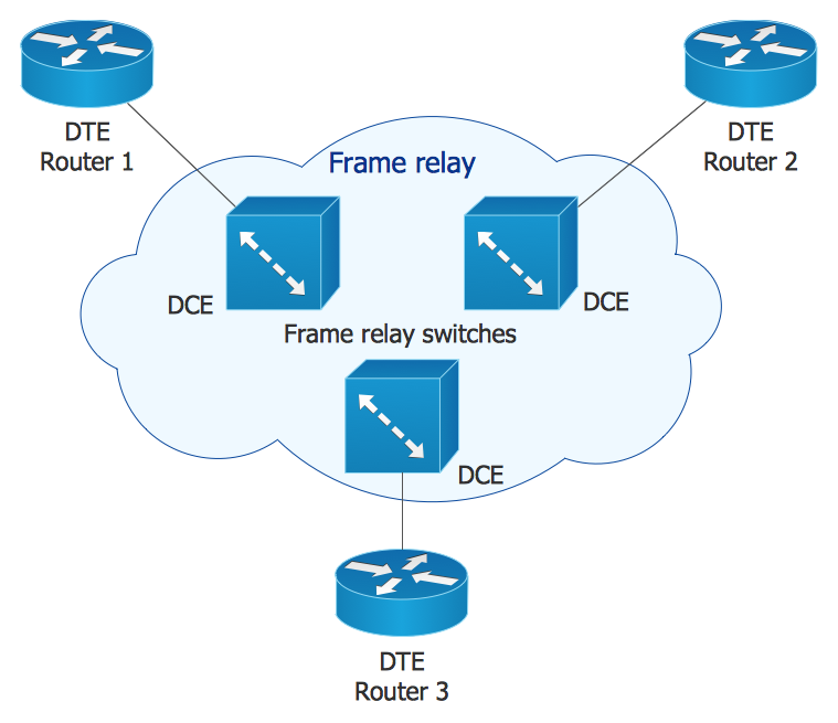
Cisco Network chart can be a great start for detailed network documentation, as well as serve as a visual instruction for new IT staff, or as a detailed illustration for a presentation. The easiest way to design Cisco Network diagram using standard Cisco product symbols is using ConceptDraw PRO powered by Cisco Network Diagrams solution. The Cisco Network Diagrams solution uses Cisco network symbols and icons to to visually document the Cisco network topology and design of Cisco network diagrams. Using ConceptDraw libraries you can access a wide array of Cisco network icons, so you can quickly prototype a new network or document an existing one.HelpDesk
How to Draw a Fire Evacuation Plan for Your Office
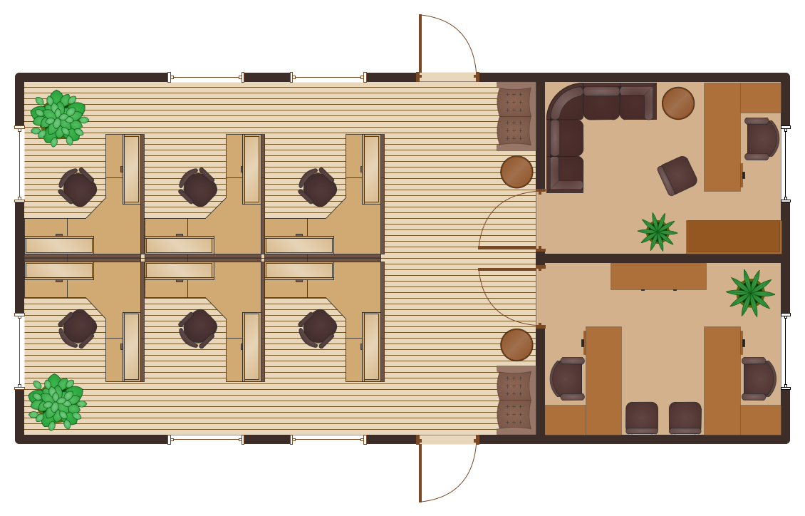
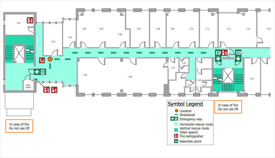
Emergency Floor Plan is important to supply an office staff with a visual safety solution. Emergency Floor Plan diagram presents a set of standard symbols used to depict fire safety, emergency, and associated information. Using clear and standard symbols on fire emergency plans delivers the coherence of collective actions , helps to avoid embarrassment, and improves communications in an emergent situation. The fire emergency symbols are intended for the general emergency and fire service, as well as for building plans ,engineering drawings and insurance diagrams. They can be used during fire extinguishing and evacuation operations, as well as training. It includes vector symbols for emergency management mapping, emergency evacuation diagrams and plans. You can use ConceptDraw PRO to make the fire evacuation plans for your office simple, accurate and easy-to-read.This office interior design sample illustrates cubicle layout of furniture on the floor plan.
"Тhe cubicle, cubicle desk, office cubicle or cubicle workstation is a partially enclosed workspace, separated from neighboring workspaces by partitions that are usually 5–6 feet (1.5–1.8 m) tall. Its purpose is to isolate office workers from the sights and noises of an open workspace so that they may concentrate without distractions. Cubicles are composed of modular elements such as work surfaces, overhead bins, drawers, and shelving, which can be configured depending on the user's needs. Installation is generally performed by professionals, although some cubicles allow configuration changes to be performed by users without specific training." [Cubicle. Wikipedia]
The office interior design example "Cubicle layout" was created using the ConceptDraw PRO diagramming and vector drawing software extended with the Office Layout Plans solution from the Building Plans area of ConceptDraw Solution Park.
HelpDesk
How to Create an IDEF0 Diagram for an Application Development
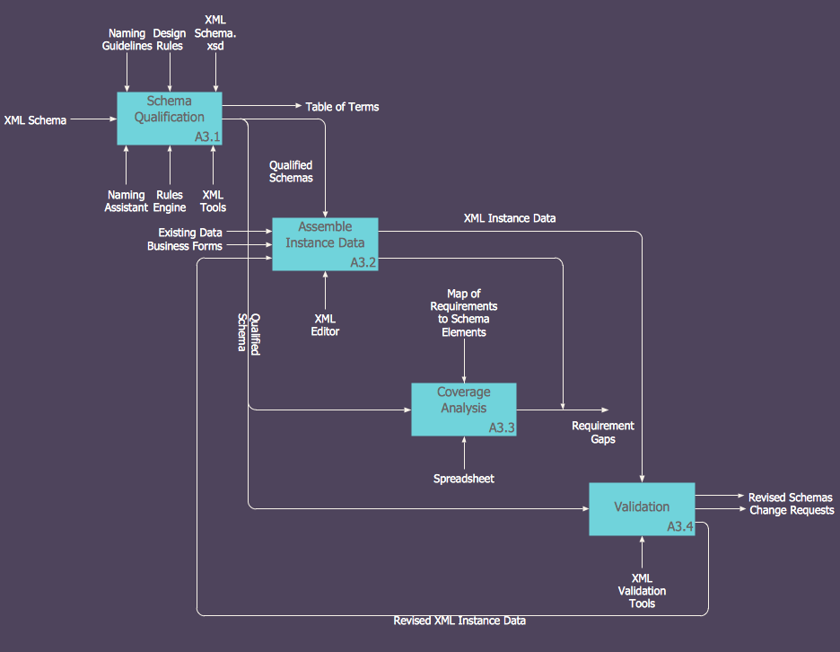
IDEF0 methods are intended to model the functions of a process, creating a graphical model that displays: what controls the function, who makes it, what resources are used and how they are connected with other functions. The IDEF0 tool is used to model the decisions, actions, and activities of a software system during the development process . IDEF0 diagram graphically depicts a model of a desired version of the application. ConceptDraw PRO allows you to create and communicate the IDEF0 diagrams of any complexity.HelpDesk
How to Open Visio® VDX File Using ConceptDraw PRO
MS Visio file with the extention .VDX can be created with the MS Visio 2003-2007. It is a filename extension for the MS Visio XML drawing file format. MS Visio 2010 and earlier versions support reading and writing files in a binary VSD or xml-based VDX file formats. Since MS Visio 2013 drawing files are written in the new VSDX and VSDM file formats. The writing VDX files is no longer supported. If you used MS Visio 2003-2010 before and now is considering to switch to ConceptDraw PRO, maybe this is a good news - ConceptDraw PRO v10 is still supported reading and writing of Microsoft Visio XML file format. Thus replacing the diagramming software , allows to keep all your drawings, created in the old versions of MS Visio. Making business drawings with ConceptDraw PRO is easier than using MS Visio. Moreover, you will be able to use a huge number of business-oriented libraries supplied by ConceptDraw Solution Park. Also, using ConceptDraw you can create your custom objects and supplement libraries to cover your requirements.- Office plan - Cubicle layout | Overhead Plan Of An Open Office
- Open Office Layout
- Open Office Work Environment
- Office Layout Plans | Emergency Plan | Product Overview | Open ...
- Open Office Workspace
- Interior Design Office Layout Plan Design Element | How to Open ...
- Open Office Workspace Design
- Open Office
- Open Office Cubicles
- Building Drawing Software for Design Seating Plan | Disadvantages ...
- Open Office Area
- Open Office Visio Equivalent
- Open Offices And Productivity
- Open Office Concept
- Open Office Productivity
- Diagram Of An Office Open Shelving
- Open Office Visio Alternative
- The Open Office
- Visio Open Office
- Open Office Design
