Made with
ConceptDraw
DIAGRAM 18

Wireless Communications

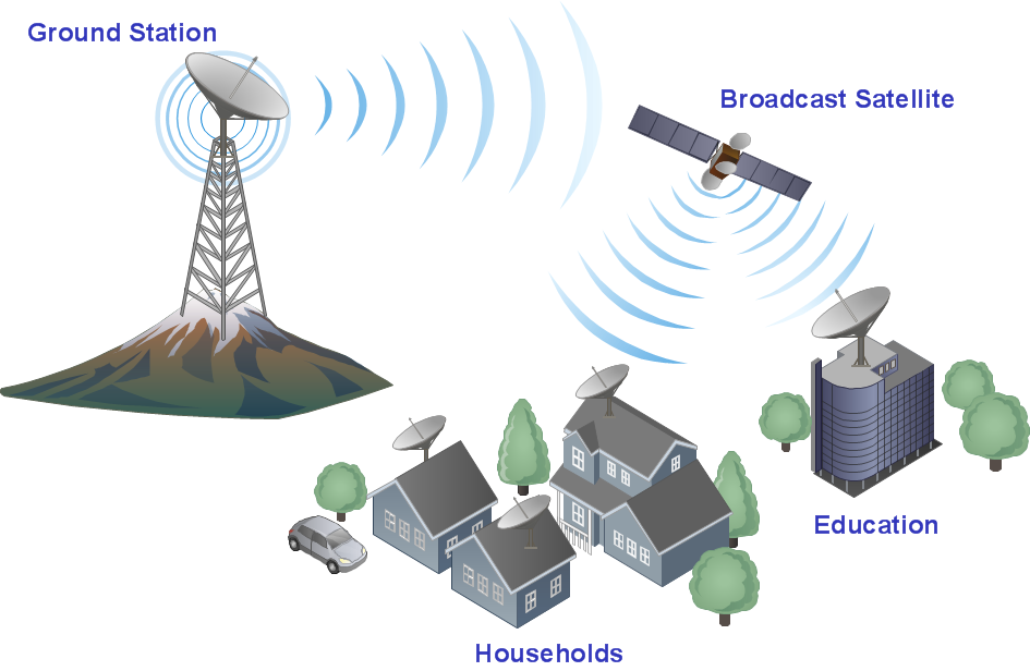
“Wireless communication is the transfer of information between two or more points that are not connected by an electrical conductor.”[from Wikipedia]

ConceptDraw DIAGRAM diagramming and vector drawing software extended with Wireless Networks Solution is the best software for fast and simple creating the Wireless Communications Diagrams.
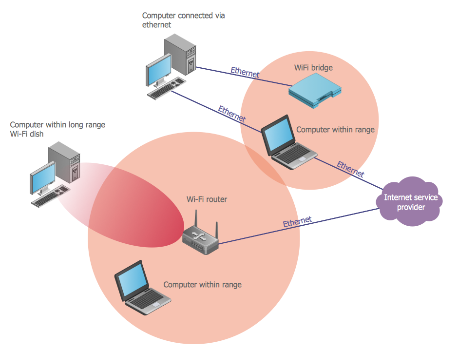
Wireless Communications *

Example 1. Wireless Communications - Wi-Fi Range Diagram

Wireless Networks Solution offers the Wireless Networks library with 81 predesigned vector stencils which will help you design wireless network diagrams in minutes. These diagrams are necessary for explaining wireless communications and successful design, mounting and support of WLANs and WWANs.
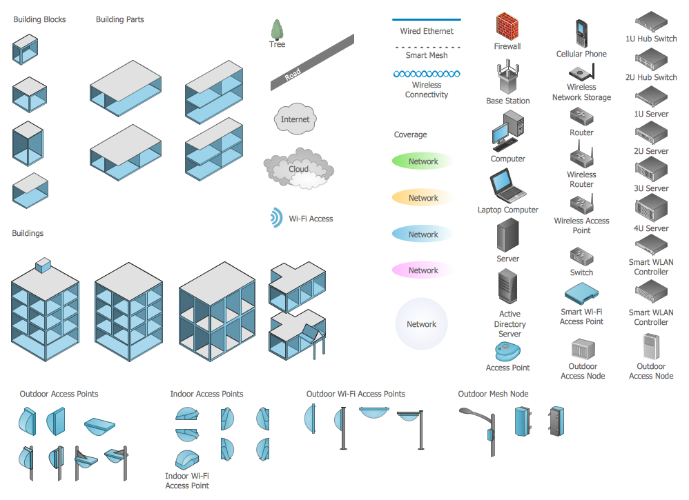
Wireless Networks Library Design Elements

Example 2. Wireless Networks Library Design Elements

Use of ready objects is the most quick way of drawing. Nothing could be easier to simply choose the needed wireless communications objects from the library, drag and arrange them.
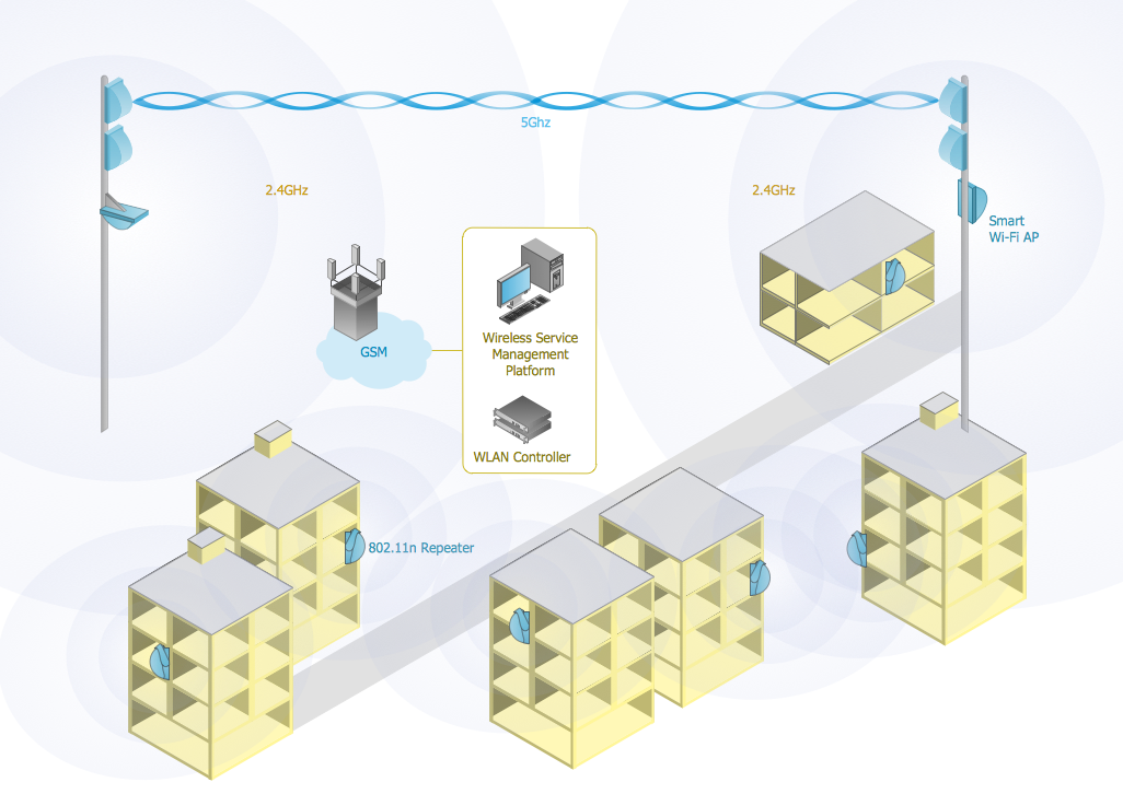
Wireless Communications - Mobile Data Offloading

Example 3. Wireless Communications - Mobile Data Offloading

The samples you see on this page were created using the Wireless Networks Solution for ConceptDraw DIAGRAM software. All these wireless communications examples are included in Wireless Networks Solution and available for viewing and editing from ConceptDraw STORE. An experienced user spent 10 minutes creating every of these diagrams.

Use the Wireless Networks Solution for ConceptDraw DIAGRAM for quick and easy creating your own professional looking wireless communications diagrams.

All source documents are vector graphic documents. They are available for reviewing, modifying, or converting to a variety of formats (PDF file, MS PowerPoint, MS Visio, and many other graphic formats) from the ConceptDraw STORE. The Wireless Networks Solution is available for all ConceptDraw DIAGRAM or later users.
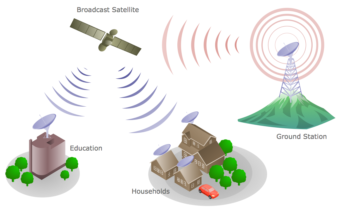


THREE RELATED HOW TO's:
Physical network represents the computer network topology that includes the computer devices, location and cable installation. Physical network includes the actual nodes, segments and hosts. This example was created in ConceptDraw DIAGRAM using the Computer and Networks Area of ConceptDraw Solution Park and shows the Physical star network.Physical network. <br>Computer and Network Examples *
Picture: Physical network. Computer and Network Examples
Related Solution:
While developing software, it is very important to have a visual model, because it helps to represent the logic and the architecture of an application. Experienced engineers use UML diagrams to denote relationships between classes and their instances. UML is a general language for a set of diagrams like deployment diagrams, object diagrams or use case diagrams. This diagram represents UML class diagram used for a software system development using an object-oriented method. Class diagrams are categorized as static structure diagrams that depict the physical structure of a system. Class diagram divides a software system's structure into "classes". Classes are defined by the methods and variables of objects. UML Class diagram is used to depict relationships and source code dependencies between objects.UML Diagram *
Picture: UML Diagram
Related Solution:
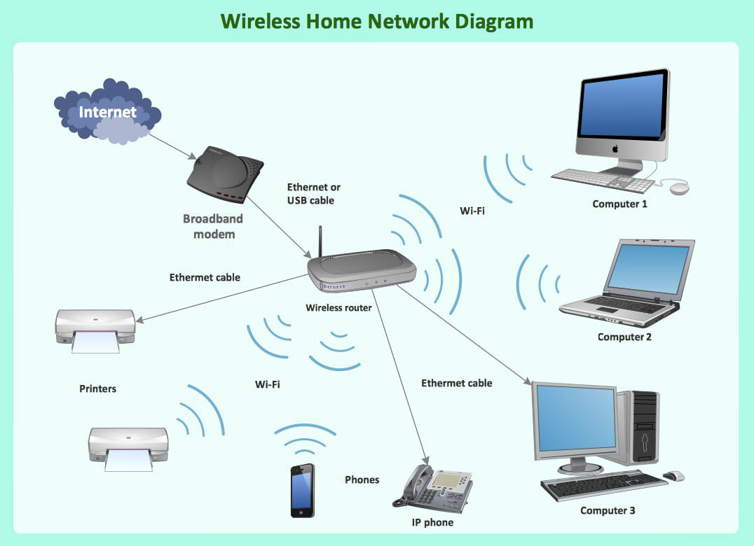
Wireless networking is useful visual tool for identification of all required equipment, and calculation the cost of creating or updating wireless computer networks. ConceptDraw DIAGRAM extended with Wireless Networks Solution from the Computer and Networks Area is the best wireless network diagramming software.Wireless Networking
Picture: Wireless Networking
Related Solution:
ConceptDraw
DIAGRAM 18