Made with
ConceptDraw
DIAGRAM 18

Network Design.
Computer and Network Examples

Network design is a complex process that include topological design, network-synthesis. In the network design process it is necessary to determine where to place the components and how to connect them. The designed network should obligatory correspond to the needs of the subscriber and operator.

ConceptDraw DIAGRAM is a powerful network diagramming and vector drawing software that allows to design professional looking networks of any complexity quick and easy. ConceptDraw DIAGRAM provides the Computer and Networks Area with many Solutions that contain the wide set of ready-to-use predesigned vector stencils and.


Network Design. <br>Computer and Network Examples *

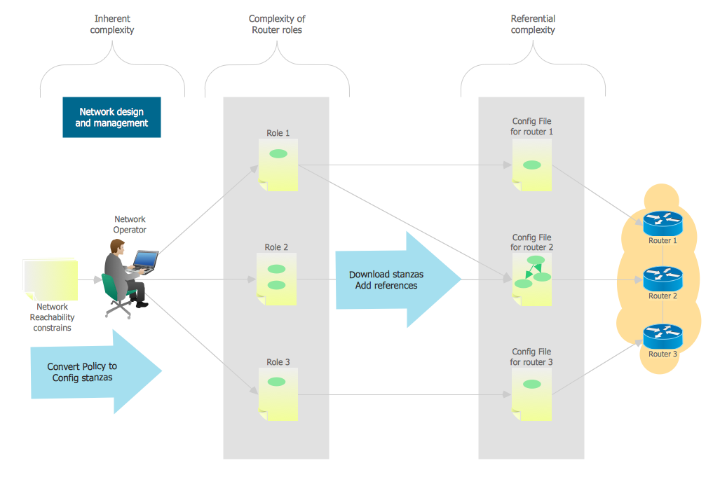
Example 1. Network Design. Computer and Network Examples

This example shows the network diagram. It was created in ConceptDraw DIAGRAM using the Computer and Networks Area of ConceptDraw Solution Park.

The network diagrams designed with ConceptDraw DIAGRAM are vector graphic documents and are available for reviewing, modifying, and converting to a variety of formats (image, HTML, PDF file, MS PowerPoint Presentation, Adobe Flash or MS Visio).


See also Samples:


THREE RELATED HOW TO's:
ConceptDraw DIAGRAM diagramming and vector drawing software extended with Fishbone Diagrams solution is a perfect tool for software designers and software developers. If you need to create Cause and Effect diagram, Fishbone diagram, Ishikawa diagram from templates and examples, or using the predesigned elements, ConceptDraw DIAGRAM can do this easily. ConceptDraw DIAGRAM software gives ability to design Fishbone diagrams that identify many possible causes for an effect for problem. Each Fishbone diagram design element included to Fishbone Diagrams library is vector and ready-to-use.Fishbone Diagram Design Element *
Picture: Fishbone Diagram Design Element
Related Solution:
In general, you can use any icons to represent network equipment on a diagram. However, there are some icons, for instance, Cisco icons, shapes, stencils and symbols, that are recognizable worldwide. Using those icons you can create Cisco network topology diagrams in minutes and share them anywhere. The icons depicting Cisco network equipment are recognized and generally applied as standard images for designing network diagrams. They are free to used , but can not be reworked. Cisco network diagrams are created to depict how signals processed on the network equipment and end-user computers and how data transfer through LAN or WLAN between nodes. The vector graphic library of ConceptDraw CISCO Network Diagrams solution includes about 90 icons of Cisco network equipment for designing computer network diagrams with ConceptDraw DIAGRAM.Cisco Network Topology. <br>Cisco icons, shapes, stencils and symbols *
Picture: Cisco Network Topology. Cisco icons, shapes, stencils and symbols
Related Solution:
Physical network represents the computer network topology that includes the computer devices, location and cable installation. Physical network includes the actual nodes, segments and hosts. This example was created in ConceptDraw DIAGRAM using the Computer and Networks Area of ConceptDraw Solution Park and shows the Physical star network.Physical network. <br>Computer and Network Examples *
Picture: Physical network. Computer and Network Examples
Related Solution:
ConceptDraw
DIAGRAM 18