Decision Tree Analysis
A decision tree can be described as a decision support tool that uses a tree-like graph. It may be also known as a model of decisions as well as their possible consequences. It can include the chance event outcomes, utility and resource costs. This representation is known to be one of the ways of displaying an algorithm that contains only conditional control statements.
Decision trees are widely used in operations research. It is mostly applied in decision analysis in order to help and identify that strategy that most likely may lead to reaching a goal. It is also known as a popular tool in machine learning, thus it worth knowing about it from this article, especially if you plan to draw a decision tree using the ConceptDraw DIAGRAM software.
A decision tree is known to be a flowchart-like structure in which each of the internal nodes represents a so-called "test" on an attribute. Each of the branches represents the outcome of the mentioned test and each of the leaf nodes represents a class label. A class label may be also described as a decision that was taken after computing all the attributes. There are paths from roots to leaves, representing the classification rules.
A decision tree, as well as the closely related influence diagrams, are commonly used in a decision analysis. They are used both as a good and convenient analytical and as visual decision support tool. The expected values of competing alternatives are known to be calculated in order to create such drawing.
Any decision tree is known to be consisting of three different types of nodes. These types include chance nodes, decision notes and end notes. First ones, chance notes, are known to be usually represented by circles. Decision nodes are usually represented with the help of squares and end nodes — by triangles.
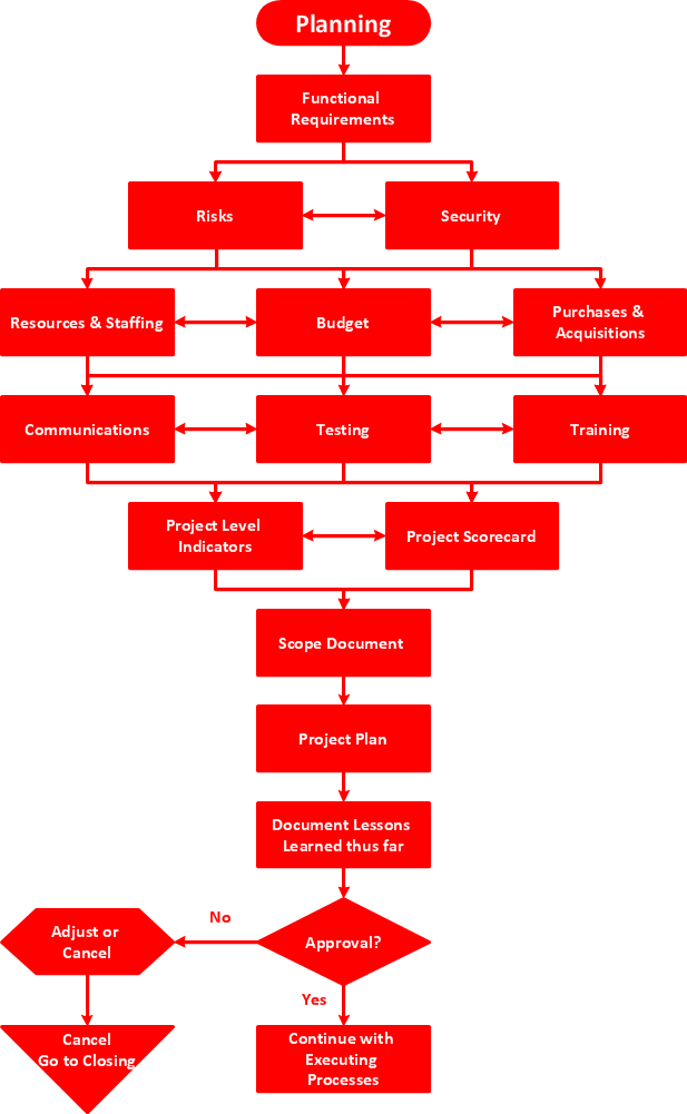
Example 1. Decision Tree Analysis
Decision trees are widely used in operations management and operations research. In case there is no recall under incomplete knowledge, a decision tree may be paralleled by the so-called probability model. It should be treated as an online selection model algorithm or the best choice model. Another use of decision trees may be as a descriptive means. It may be used for calculating the conditional probabilities.
Decision trees, utility functions, influence diagrams as well as other decision analysis methods and tools may be taught to students in schools of health economics, public health and different kinds of business activity.
A decision tree that is drawn from left to right has only burst nodes known as splitting paths. At the same time, there are no sink nodes (also known as the so-called “converging paths”). Nevertheless, they can grow large, being often hard to draw totally by hand. Usually, decision trees have been created manually. Nowadays there is no need for making such drawings by hand as the specialized software was employed.
The ConceptDraw DIAGRAM diagramming and drawing software is the one that can help with creating the needed drawing, including a decision tree. Making decision tree analysis, it is always easy to make the needed matrix as there are plenty of pre-made templates to be used.

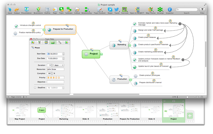
Example 2. Decision Making Tree
Any decision tree can be linearized into the so-called decision rules. The outcome is expected to be the contents of the leaf node. The conditions along the path are known to be forming a conjunction in the “if” clause. Decision rules can be created followed by constructing the so-called association rules. They normally have the target variable on the right, being denoting either causal or temporal relations.
The decision tree may be created by using the most commonly used flowchart symbols. Such symbols are usually normal flowchart design elements, so it is easier for many to read and to understand the result of such drawing.
The Decision Making solution offers the pre-made templates and samples of the decision-making related drawings that all can be used as drafts for drawing the unique looking illustrations. Also, there are stencil libraries full of design symbols that can be always taken by any ConceptDraw DIAGRAM user in order to complete the needed tasks of drawing.
Decision tree as a commonly used decision support tool has several advantages. Thus, they are simple to understand and so to interpret. People can understand decision tree models once a brief explanation was offered. Having value with little hard data, the important insights can be generated with the help of ConceptDraw DIAGRAM software in order to create the needed decision tree. Being based on the experts’ opinion while describing a situation mentioning the alternatives, costs and probabilities, the decision trees should be created taking into consideration the preferences for outcomes as well.
Allowing the addition of new possible scenarios, any pre-made decision-making related drawing from the Decision Making solution may be edited when it is needed. Helping to determine best, worst as well as the expected values for different scenarios, the decision trees can be made while working in the ConceptDraw DIAGRAM diagramming and vector drawing software within a few minutes as long as the Decision Making solution is being used.