Antenna TV
A television antenna is the type of antenna intended for using with a television receiver, which catches over-the-air broadcast television signals produced by a television station. Being captured from the television station by antenna TV, the radio waves are converted into radio frequency alternating currents. Then the television tuner is applied to extract the television signal.
There are indoor and outdoor television antennas. The indoor antennas are cheaper and are installed next to the television. The outdoor antennas are more expensive and more difficult to install, they are mounted on tops of houses, lofts, or attics. This makes some danger during installing or adjusting a TV antenna. Furthermore, TV antennas are good conductors of electricity and attract lightning, therefore the mounting of a lightning arrestor (a large grounding rod) is obligatory to protect against this. However, outdoor antennas are an efficient choice in areas distant from television stations or where the TV signal of some channels is spotty, breaks for obstructions, or does not exist. In these cases, the outdoor antennas give access to popular TV programs, news, movies, shows, sports, etc. Plus, sometimes an indoor antenna is installed in addition to an outdoor TV antenna.
There are dipole and loop indoor antennas. Among the outdoor antennas are Yagi, log periodic, and multi-bay reflective array antennas.
A specialized cable is used to connect the antenna to the television. Currently, 75 Ohm coaxial cable is used for the transmission lines. Initially, 300 Ohm twin-lead cables were used. The coaxial cables are more relevant because of less susceptible to interference, however, the twin-lead lines are still in use. To convert the signal from antennas using twin-lead lines to the coaxial cable input are used the transformers.
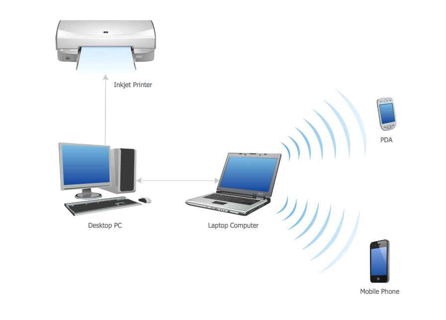
Example 1. Antenna TV
Television broadcasting is realized in different bands:
- VHF (very high frequency) low band or band I - from 47 to 68 MHz;
- VHF high band or band III - from 174 to 216 MHz;
- ultra-high frequency (UHF) band or band IV and V - from 470 to 698 MHz.
The boundaries of each band can slightly differ in various countries. The area's terrain makes the adjustments because the radio waves proceed by line-of-sight and are blocked by hills. Moreover, the television station's reception area is limited by 40–60 miles or 65–95 km.
ConceptDraw DIAGRAM software supplied with Telecom and AV Circuits solution offers wide abilities for designing thematic diagrams, infographics and illustrations. You can easily create illustrative reviews of TV antennas, show the different types of TV antennas from the basic indoor antennas to amplified outdoor antennas, identify their advantages and gaps. You can offer the testing results to help detect the best TV antenna from the variety available on the market. It is also a way to illustrate the connection of antennas, how to position them to get the best reception, which channels are available and how to set up your equipment.

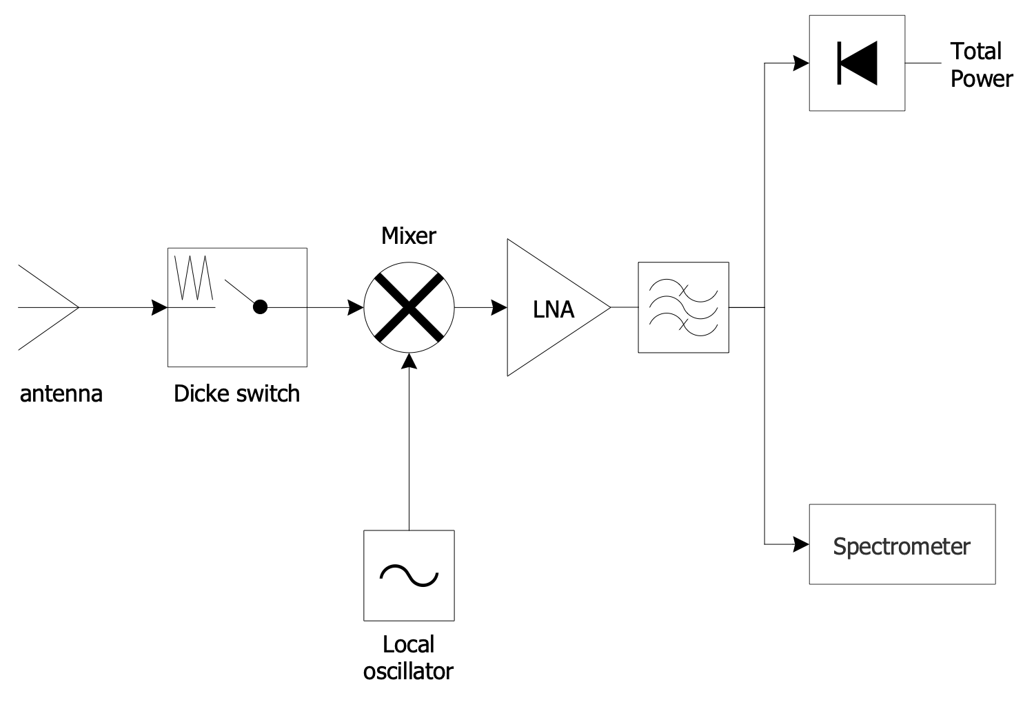
Example 2. FM Receiver Circuit
Telecom and AV Circuits provides 7 libraries with numerous pre-made vector design elements:
- Design Elements — Antennas and Waveguides
- Design Elements — Audio Circuits
- Design Elements — Radio Stations
- Design Elements — Telegraph Circuits
- Design Elements — Telephone Handsets
- Design Elements — VHF, UHF, SHF
- Design Elements — Video and TV Circuits

Example 3. Radio Communications
The Telecom and AV Circuits samples you see on this page were created in ConceptDraw DIAGRAM software using the drawing tools of the Telecom and AV Circuits Solution. These examples successfully demonstrate the solution's capabilities and the professional results you can achieve using it. An experienced user spent 5-15 minutes creating each of these samples.
Use the drawing tools of the Telecom and AV Circuits solution to design your own Telecom and AV Circuits diagrams and infographics quick, easy, and effective.
All source documents are vector graphic documents. They are available for reviewing, modifying, or converting to a variety of formats (PDF file, MS PowerPoint, MS Visio, and many other graphic formats) from the ConceptDraw STORE. The Telecom and AV Circuits Solution is available for ConceptDraw DIAGRAM users.