Network Diagram Software Home Area Network


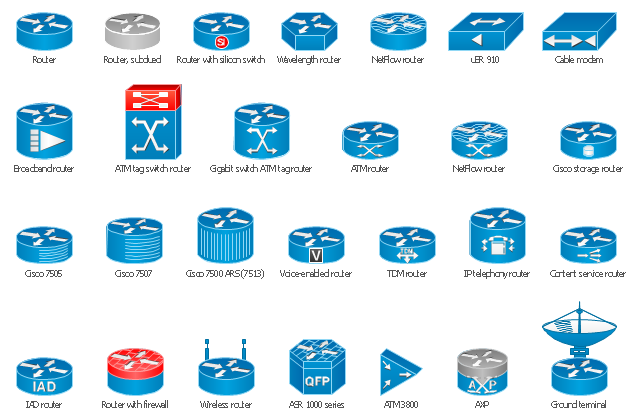
The vector stencils library "Cisco routers" contains 27 router symbols for drawing the Cisco computer network diagrams using the ConceptDraw PRO diagramming and vector drawing software.
"A router is a device that forwards data packets between computer networks, creating an overlay internetwork. A router is connected to two or more data lines from different networks. When a data packet comes in one of the lines, the router reads the address information in the packet to determine its ultimate destination. Then, using information in its routing table or routing policy, it directs the packet to the next network on its journey. Routers perform the "traffic directing" functions on the Internet. A data packet is typically forwarded from one router to another through the networks that constitute the internetwork until it reaches its destination node.
The most familiar type of routers are home and small office routers that simply pass data, such as web pages, email, IM, and videos between the home computers and the Internet. An example of a router would be the owner's cable or DSL modem, which connects to the Internet through an ISP. More sophisticated routers, such as enterprise routers, connect large business or ISP networks up to the powerful core routers that forward data at high speed along the optical fiber lines of the Internet backbone. Though routers are typically dedicated hardware devices, use of software-based routers has grown increasingly common." [Router (computing). Wikipedia]
The example "Design elements - Cisco routers" is included in the Cisco Network Diagrams solution from the Computer and Networks area of ConceptDraw Solution Park.
Cisco router symbols
Wireless Network Mode

The vector stencils library "Computers and network isometric" contains 56 3D clipart images of computer and network devices and equipment for drawing network diagrams.
The clip art example "Computers and network isometric - Vector stencils library" was created using the ConceptDraw PRO diagramming and vector drawing software extended with the Computer and Networks solution from the Computer and Networks area of ConceptDraw Solution Park.
The clip art example "Computers and network isometric - Vector stencils library" was created using the ConceptDraw PRO diagramming and vector drawing software extended with the Computer and Networks solution from the Computer and Networks area of ConceptDraw Solution Park.
Laptop

DDCS

Server

Webcam

Wireless Network Storage

Personal computer

VoIP phone

Fax

Plotter

Mobile phone

Feature phone

Printer

Satellite dish

Satellite antenna

Automatic-tracking satellite dish
Wireless access point

Wireless router

Router

Network switch

Network device

Mobile GPS Terminal

GPS phone

Television antenna

Radio tower

Base station

Satellite

In-vehicle satellite telecommunication

Satellite dishes on ship

Airplane

Internet

Man

Woman

Call-center

Honeycomb

Mountain

Radio waves

Radio waves

Tower block

Office building

House

House

Globe

Wireless security camera

Truck

Tree

Conifer tree

1U hub / switch

2U hub / switch

1U server

2U Server

3U Server

4U Server

Communications satellite

Car

Radio waves

Firewall

Home Networking

How To use Building Plan Examples


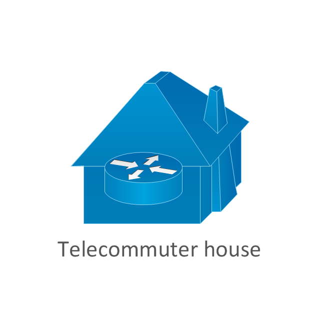
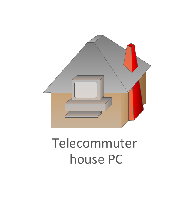
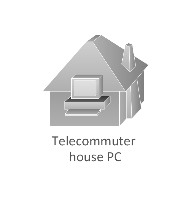
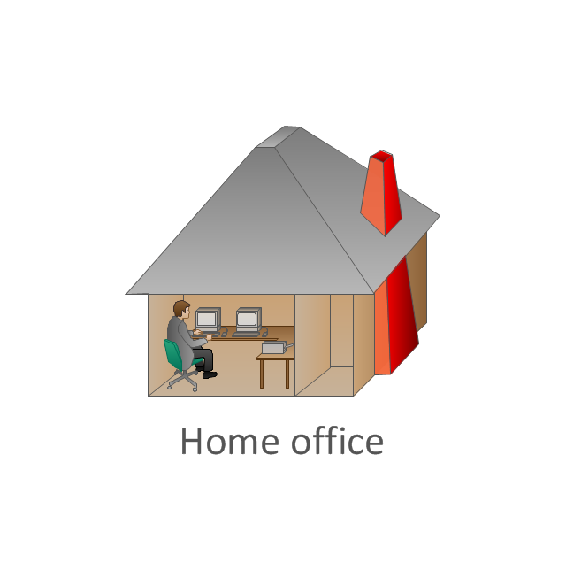
The vector stencils library "Cisco buildings" contains 21 symbols: Government building, University, Small business, Branch office, Headquarters, Router in building, House, Telecommuter house, Home office, Medium building, Multidwelling unit (MDU), Mediator.
The symbols example "Cisco buildings - Vector stencils library" was created using the ConceptDraw PRO diagramming and vector drawing software extended with the Cisco Network Diagrams solution from the Computer and Networks area of ConceptDraw Solution Park.
www.conceptdraw.com/ solution-park/ computer-networks-cisco
Government building
University
Small business
Branch Office, regular

Branch Office, blue
Branch Office, subdued
Headquarters
Headquarters, blue
Headquarters, subdued
Building with router
House, regular
House, blue
Telecommuter house
Telecommuter house PC
Telecommuter house PC, subdued
Home office
Medium building, regular
Medium building, blue
Medium building, subdued
MDU
Mediator
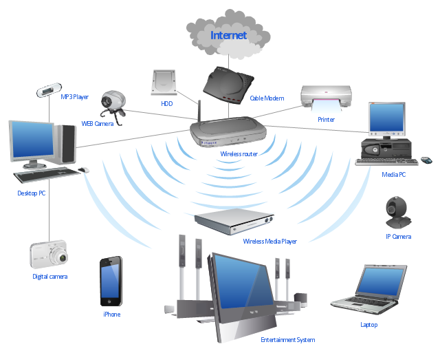
"A wireless network is any type of computer network that uses wireless data connections for connecting network nodes. Wireless networking is a method by which homes, telecommunications networks and enterprise (business) installations avoid the costly process of introducing cables into a building, or as a connection between various equipment locations. Wireless telecommunications networks are generally implemented and administered using radio communication. This implementation takes place at the physical level (layer) of the OSI model network structure. Examples of wireless networks include cell phone networks, Wi-Fi local networks and terrestrial microwave networks." [Wireless network. Wikipedia]
This wireless router network diagram example was created using the ConceptDraw PRO diagramming and vector drawing software extended with the Computer and Networks solution from the Computer and Networks area of ConceptDraw Solution Park.
This wireless router network diagram example was created using the ConceptDraw PRO diagramming and vector drawing software extended with the Computer and Networks solution from the Computer and Networks area of ConceptDraw Solution Park.
Network diagram
Used Solutions
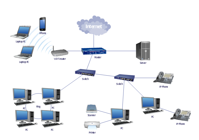
"A local area network (LAN) is a computer network that interconnects computers in a limited area such as a home, school, computer laboratory, or office building using network media. The defining characteristics of LANs, in contrast to wide area networks (WANs), include their smaller geographic area, and non-inclusion of leased telecommunication lines. Ethernet over twisted pair cabling, and Wi-Fi are the two most common technology standards currently used to build LANs." [Local area network. Wikipedia]
This local area network (LAN) topology diargam example was created using the ConceptDraw PRO diagramming and vector drawing software extended with the Computer and Networks solution from the Computer and Networks area of ConceptDraw Solution Park.
This local area network (LAN) topology diargam example was created using the ConceptDraw PRO diagramming and vector drawing software extended with the Computer and Networks solution from the Computer and Networks area of ConceptDraw Solution Park.
LAN topology diagram
Local area network (LAN). Computer and Network Examples
 diagram")
The vector stencils library "Logical symbols" contains 49 logical symbols for drawing logical network topology diagrams.
"Logical topology, or signal topology, is the arrangement of devices on a computer network and how they communicate with one another. How devices are connected to the network through the actual cables that transmit data, or the physical structure of the network, is called the physical topology. Physical topology defines how the systems are physically connected. It represents the physical layout of the devices on the network. The logical topology defines how the systems communicate across the physical topologies.
Logical topologies are bound to network protocols and describe how data is moved across the network. ... EXAMPLE : twisted pair Ethernet is a logical bus topology in a physical star topology layout. While IBM's token ring is a logical ring topology, it is physically set up in star topology." [Logical topology. Wikipedia]
The icons example "Logical symbols - Vector stencils library" was created using the ConceptDraw PRO diagramming and vector drawing software extended with the Computer and Networks solution from the Computer and Networks area of ConceptDraw Solution Park.
www.conceptdraw.com/ solution-park/ computer-and-networks
Coaxial Line Tag

Fiber Optic Line Tag

Twisted Pair Line Tag

SC2200 Signaling Controller

Bridge

Network Management Appliance

Access Server (Communications Server)
-logical-symbols---vector-stencils-library.png--diagram-flowchart-example.png)
Terminal Server

Web Browser

Security Management, Cisco

Lock and Key

Lock

Key

Relational Database

Host

CSU/DSU

WAN

University

Government building

Home Office

Telecommuter House PC

Medium Building, Regular

Headquarters, Subdued

House, Regular

Small Business

Network Connector

Dynamic Connector

Line Connector

Line-curve Connector

Bus

FDDI Ring

Peer-to-peer

Token-ring

Star

Comm-link

Curved Bus

Ethernet

Cloud

Speaker

Microphone

Router

ATM Router

ISDN Switch

ATM Switch

ATM/FastGB Etherswitch

Workgroup Switch

Small Hub

100BaseT Hub

CDDI-FDDI

The vector stencils library "Logical symbols" contains 49 logical symbols for drawing logical network topology diagrams.
"Logical topology, or signal topology, is the arrangement of devices on a computer network and how they communicate with one another. How devices are connected to the network through the actual cables that transmit data, or the physical structure of the network, is called the physical topology. Physical topology defines how the systems are physically connected. It represents the physical layout of the devices on the network. The logical topology defines how the systems communicate across the physical topologies.
Logical topologies are bound to network protocols and describe how data is moved across the network. ... EXAMPLE : twisted pair Ethernet is a logical bus topology in a physical star topology layout. While IBM's token ring is a logical ring topology, it is physically set up in star topology." [Logical topology. Wikipedia]
The icons example "Logical symbols - Vector stencils library" was created using the ConceptDraw PRO diagramming and vector drawing software extended with the Computer and Networks solution from the Computer and Networks area of ConceptDraw Solution Park.
www.conceptdraw.com/ solution-park/ computer-and-networks
"Logical topology, or signal topology, is the arrangement of devices on a computer network and how they communicate with one another. How devices are connected to the network through the actual cables that transmit data, or the physical structure of the network, is called the physical topology. Physical topology defines how the systems are physically connected. It represents the physical layout of the devices on the network. The logical topology defines how the systems communicate across the physical topologies.
Logical topologies are bound to network protocols and describe how data is moved across the network. ... EXAMPLE : twisted pair Ethernet is a logical bus topology in a physical star topology layout. While IBM's token ring is a logical ring topology, it is physically set up in star topology." [Logical topology. Wikipedia]
The icons example "Logical symbols - Vector stencils library" was created using the ConceptDraw PRO diagramming and vector drawing software extended with the Computer and Networks solution from the Computer and Networks area of ConceptDraw Solution Park.
www.conceptdraw.com/ solution-park/ computer-and-networks
Coaxial Line Tag
Fiber Optic Line Tag
Twisted Pair Line Tag
SC2200 Signaling Controller
Bridge
Network Management Appliance
Access Server (Communications Server)
Terminal Server
Web Browser
Security Management, Cisco
Lock and Key
Lock
Key
Relational Database
Host
CSU/DSU
WAN
University
Government building
Home Office
Telecommuter House PC
Medium Building, Regular
Headquarters, Subdued
House, Regular
Small Business
Network Connector
Dynamic Connector
Line Connector
Line-curve Connector
Bus
FDDI Ring
Peer-to-peer
Token-ring
Star
Comm-link
Curved Bus
Ethernet
Cloud
Speaker
Microphone
Router
ATM Router
ISDN Switch
ATM Switch
ATM/FastGB Etherswitch
Workgroup Switch
Small Hub
100BaseT Hub
CDDI-FDDI
Cisco Network Icons

 Wireless Networks
The Wireless Networks Solution extends ConceptDraw DIAGRAM software with professional diagramming tools, set of wireless network diagram templates and samples, comprehensive library of wireless communications and WLAN objects to help network engineers and designers efficiently design and create Wireless network diagrams that illustrate wireless networks of any speed and complexity, and help to identify all required equipment for construction and updating wireless networks, and calculating their costs.
Colored Baseball Field Diagram

Network Gateway Router

Cisco Routers. Cisco icons, shapes, stencils and symbols

Network Security Devices

Fully Connected Network Topology Diagram

This exaple was resigned from the Wikimedia Commons file: Mobile Cloud Architecture.jpg. [commons.wikimedia.org/ wiki/ File:Mobile_ Cloud_ Architecture.jpg]
This file is licensed under the Creative Commons Attribution-Share Alike 3.0 Unported license. [creativecommons.org/ licenses/ by-sa/ 3.0/ deed.en]
This diagram describes general architecture of Mobile Cloud Computing.
Legend.
BTS: Base Transceiver Station.
AAA: Network Authentication, Authorization, and Accounting.
HA: Home Agent.
"Mobile/ cloud computing is the combination of cloud computing and mobile networks to bring benefits for mobile users, network operators, as well as cloud computing providers. The ultimate goal of MCC (mean of MCC is Mobile/ Cloud Computing) is to enable execution of rich mobile applications on a plethora of mobile devices, with a rich user experience. MCC provides business opportunities for mobile network operators as well as cloud providers." [Mobile cloud computing. Wikipedia]
The example "Mobile cloud architecture diagram" was created using the ConceptDraw PRO diagramming and vector drawing software extended with the AWS Architecture Diagrams solution from the Computer and Networks area of ConceptDraw Solution Park.
AWS cloud architecture diagram

- Wireless router network diagram | Network Diagram Examples ...
- Design elements - Cisco routers | Network Gateway Router | Cisco ...
- Network Diagram Software | Network Gateway Router | Posnal ...
- Network Gateway Router | ConceptDraw Arrows10 Technology ...
- Lan Network Diagram With Wireless Router
- Wireless router network diagram | Wireless Network Mode | What Is ...
- Home area networks (HAN). Computer and Network Examples ...
- Cisco Routers . Cisco icons, shapes, stencils and symbols | Wireless ...
- Network Gateway Router | 3d Home Spesilist Picture Digrame
- Router
- Wireless router network diagram
- Wireless router network diagram | Wireless access point | Computer ...
- Wireless Networks | Block Diagram Of Wifi Router
- Wireless router network diagram | Wireless Network Mode | Cisco ...
- Cisco Routers . Cisco icons, shapes, stencils and symbols | Star ...
- Wireless access point | Hotel Network Topology Diagram | How to ...
- Network Printer | Wireless access point - Network diagram | Wireless ...
- Network Gateway Router | Computer Network Diagrams | How To ...
- Design elements - Cisco routers | Cisco routers - Vector stencils ...
- Electrical Symbols — Qualifying | Network Diagram Software Home ...