This HVAC schematic sample was drawn on the base of Wikimedia Commons file: Online Auxiliar Water Heater Diagram.svg.
[commons.wikimedia.org/ wiki/ File:Online_ Auxiliar_ Water_ Heater_ Diagram.svg]
This file is licensed under the Creative Commons Attribution-Share Alike 3.0 Unported license. [creativecommons.org/ licenses/ by-sa/ 3.0/ deed.en]
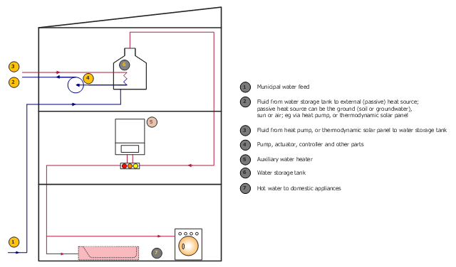
"A central heating system provides warmth to the whole interior of a building (or portion of a building) from one point to multiple rooms. When combined with other systems in order to control the building climate, the whole system may be an HVAC (heating, ventilation and air conditioning) system. ...
A district heating system uses centrally located boilers or water heaters and circulates heat energy to individual customers by circulating hot water or steam. This has the advantage of a central highly efficient energy converter than can use the best available pollution controls, and that is professionally operated. The district heating system can use heat sources impractical to deploy to individual homes, such as heavy oil, wood byproducts, or (hypothetically) nuclear fission. The distribution network is more costly to build than for gas or electric heating, and so is only found in densely populated areas or compact communities." [Central heating. Wikipedia]
The HVAC schematic example "Online auxiliary water heater" was designed using ConceptDraw DIAGRAM software extended with HVAC Plans solution from the Building Plans area of ConceptDraw Solution Park.
[commons.wikimedia.org/ wiki/ File:Online_ Auxiliar_ Water_ Heater_ Diagram.svg]
This file is licensed under the Creative Commons Attribution-Share Alike 3.0 Unported license. [creativecommons.org/ licenses/ by-sa/ 3.0/ deed.en]
"A central heating system provides warmth to the whole interior of a building (or portion of a building) from one point to multiple rooms. When combined with other systems in order to control the building climate, the whole system may be an HVAC (heating, ventilation and air conditioning) system. ...
A district heating system uses centrally located boilers or water heaters and circulates heat energy to individual customers by circulating hot water or steam. This has the advantage of a central highly efficient energy converter than can use the best available pollution controls, and that is professionally operated. The district heating system can use heat sources impractical to deploy to individual homes, such as heavy oil, wood byproducts, or (hypothetically) nuclear fission. The distribution network is more costly to build than for gas or electric heating, and so is only found in densely populated areas or compact communities." [Central heating. Wikipedia]
The HVAC schematic example "Online auxiliary water heater" was designed using ConceptDraw DIAGRAM software extended with HVAC Plans solution from the Building Plans area of ConceptDraw Solution Park.
This mechanical systems drawing sample was designed on the base of Wikimedia Commons file: Building services coordinated drawing.JPG.
[commons.wikimedia.org/ wiki/ File:Building_ services_ coordinated_ drawing.JPG ]
This file is licensed under the Creative Commons Attribution-Share Alike 3.0 Unported license. [creativecommons.org/ licenses/ by-sa/ 3.0/ deed.en]
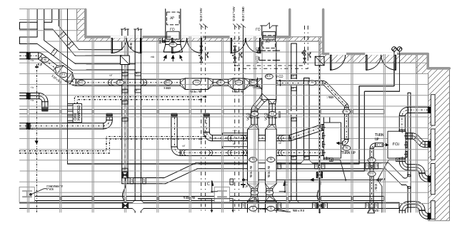
"Mechanical systems drawing is a type of technical drawing that shows information about heating, ventilating, air conditioning and transportation around the building (Elevators or Lifts and Escalator). It is a powerful tool that helps analyze complex systems. These drawings are often a set of detailed drawings used for construction projects; it is a requirement for all HVAC work. They are based on the floor and reflected ceiling plans of the architect. After the mechanical drawings are complete, they become part of the construction drawings, which is then used to apply for a building permit. They are also used to determine the price of the project." [Mechanical systems drawing. Wikipedia]
The mechanical systems drawing example "Building services coordinated drawing" was designed using ConceptDraw DIAGRAM software extended with HVAC Plans solution from the Building Plans area of ConceptDraw Solution Park.
[commons.wikimedia.org/ wiki/ File:Building_ services_ coordinated_ drawing.JPG ]
This file is licensed under the Creative Commons Attribution-Share Alike 3.0 Unported license. [creativecommons.org/ licenses/ by-sa/ 3.0/ deed.en]
"Mechanical systems drawing is a type of technical drawing that shows information about heating, ventilating, air conditioning and transportation around the building (Elevators or Lifts and Escalator). It is a powerful tool that helps analyze complex systems. These drawings are often a set of detailed drawings used for construction projects; it is a requirement for all HVAC work. They are based on the floor and reflected ceiling plans of the architect. After the mechanical drawings are complete, they become part of the construction drawings, which is then used to apply for a building permit. They are also used to determine the price of the project." [Mechanical systems drawing. Wikipedia]
The mechanical systems drawing example "Building services coordinated drawing" was designed using ConceptDraw DIAGRAM software extended with HVAC Plans solution from the Building Plans area of ConceptDraw Solution Park.
- Automobile Air Conditioning Wiki
- Air Control Valve Wikipedia
- Atmosphere air composition | Air handler- HVAC plan | Air ...
- Ventilation unit with heat pump and ground heat exchanger ...
- Elements location of a welding symbol | Elements location of a ...
- Blow-through unit ventilator - HVAC plan | Ventilation unit with heat ...
- House ventilation | Ventilation unit with heat pump and ground heat ...
- Air handler- HVAC plan | HVAC control equipment - Vector stencils ...
- Block Diagrams | Design elements - HVAC control equipment ...
- Heating Equipment Hvac Control