Software development with ConceptDraw Products

"Inspection in software engineering, refers to peer review of any work product by trained individuals who look for defects using a well defined process. An inspection might also be referred to as a Fagan inspection after Michael Fagan, the creator of a very popular software inspection process. ...
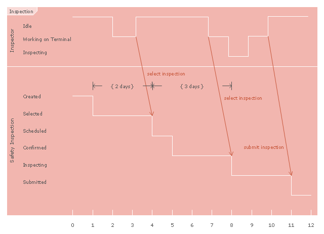
An inspection is one of the most common sorts of review practices found in software projects. The goal of the inspection is for all of the inspectors to reach consensus on a work product and approve it for use in the project. Commonly inspected work products include software requirements specifications and test plans. In an inspection, a work product is selected for review and a team is gathered for an inspection meeting to review the work product. A moderator is chosen to moderate the meeting. Each inspector prepares for the meeting by reading the work product and noting each defect. The goal of the inspection is to identify defects. In an inspection, a defect is any part of the work product that will keep an inspector from approving it. For example, if the team is inspecting a software requirements specification, each defect will be text in the document which an inspector disagrees with." [Software inspection. Wikipedia]
The UML timing diagram example "Inspection" was created using the ConceptDraw PRO diagramming and vector drawing software extended with the Rapid UML solution from the Software Development area of ConceptDraw Solution Park.
UML timing diagram
"Component diagram shows components, provided and required interfaces, ports, and relationships between them. This type of diagrams is used in Component-Based Development (CBD) to describe systems with Service-Oriented Architecture (SOA).
Component-based development is based on assumptions that previously constructed components could be reused and that components could be replaced by some other "equivalent" or "conformant" components, if needed.
The artifacts that implement component are intended to be capable of being deployed and re-deployed independently, for instance to update an existing system.
Components in UML could represent:
(1) logical components (e.g., business components, process components), and
(2) physical components (e.g., CORBA components, EJB components, COM+ and .NET components, WSDL components, etc.),
along with the artifacts that implement them and the nodes on which they are deployed and executed. It is anticipated that profiles based around components will be developed for specific component technologies and associated hardware and software environments." [uml-diagrams.org/ component-diagrams.html]
The template "UML component diagram" for the ConceptDraw PRO diagramming and vector drawing software is included in the Rapid UML solution from the Software Development area of ConceptDraw Solution Park.
www.conceptdraw.com/ solution-park/ software-uml
UML component diagram

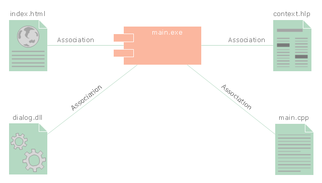
"In the Unified Modeling Language, a component diagram depicts how components are wired together to form larger components and or software systems. They are used to illustrate the structure of arbitrarily complex systems." [Component diagram. Wikipedia]
This UML component diagram example was created using the ConceptDraw PRO diagramming and vector drawing software extended with the Rapid UML solution from the Software Development area of ConceptDraw Solution Park.
This UML component diagram example was created using the ConceptDraw PRO diagramming and vector drawing software extended with the Rapid UML solution from the Software Development area of ConceptDraw Solution Park.
UML component diagram
 Rapid UML
Rapid UML solution extends ConceptDraw PRO software with templates, samples and libraries of vector stencils for quick drawing the UML diagrams using Rapid Draw technology.
 Software Development
This solution extends ConceptDraw PRO v9.4 and helps to accelerate and simplify software development and design by allowing you to draw UML diagrams and prototype Windows and Mac OS user interfaces.
 Frequency Distribution Dashboard
Frequency distribution dashboard solution extends ConceptDraw PRO software with samples, templates and vector stencils libraries with histograms and area charts for drawing the visual dashboards showing frequency distribution of data.
The vector stencils library "UML component diagrams" contains 36 symbols for the ConceptDraw PRO diagramming and vector drawing software.
"In the Unified Modeling Language, a component diagram depicts how components are wired together to form larger components and or software systems. They are used to illustrate the structure of arbitrarily complex systems. ...
Symbols.
This may have a visual stereotype in the top right of the rectangle of a small rectangle with two even smaller rectangles jutting out on the left.
The lollipop, a small circle on a stick represents an implemented or provided interface. The socket symbol is a semicircle on a stick that can fit around the lollipop. This socket is a dependency or needed interface." [Component diagram. Wikipedia]
The example "Design elements - UML component diagrams" is included in the Rapid UML solution from the Software Development area of ConceptDraw Solution Park.
UML component diagram symbols

 Marketing
This solution extends ConceptDraw PRO v9 and ConceptDraw MINDMAP v7 with Marketing Diagrams and Mind Maps (brainstorming, preparing and holding meetings and presentations, sales calls).
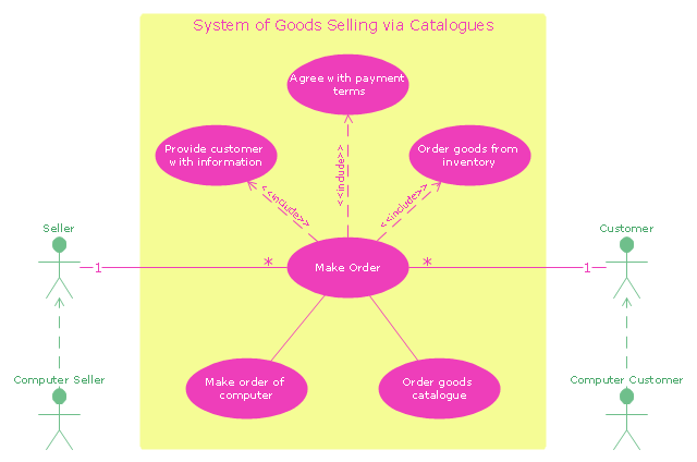
"A catalog merchant (catalogue merchant in British and Canadian English) is a form of retailing. The typical merchant sells a wide variety of household and personal products, with many emphasizing jewelry. Unlike a self-serve retail store, most of the items are not displayed; customers select the products from printed catalogs in the store and fill out an order form. The order is brought to the sales counter, where a clerk retrieves the items from the warehouse area to a payment and checkout station. ...
The catalog merchant has generally lower prices than other retailers and lower overhead expenses due to the smaller size of store and lack of large showroom space.
There are a few key benefits to this approach. By operating as an in-store catalog sales center, it could be exempt from the "Resale price maintenance" policy of the manufacturers, which can force conventional retailers to charge a minimum sales price to prevent price-cutting competition; it also reduces the risk of merchandise theft, known in the industry as shrinkage.
From the consumer's point of view, there are potential advantages and disadvantages. The catalog showroom approach allows customers to shop without having to carry their purchases throughout the store as they shop. Possible downsides include that customers may be required to give their contact information when an order is placed, take the time to fill out order forms, and wait a period of time for their order to be available for purchase. This wait may be days long, one of the chief vulnerabilities of the catalog showroom approach." [Catalog merchant. Wikipedia]
The UML use case diagram example "System of goods selling via catalogues" was created using the ConceptDraw PRO diagramming and vector drawing software extended with the Rapid UML solution from the Software Development area of ConceptDraw Solution Park.
UML use case diagram
 PM Meetings
This solution extends ConceptDraw MINDMAP software, by making meeting preparation a quick and simple task.
- Resources and TEAF Work Products for EA Direction, Description ...
- Think. Act. Accomplish. | Product Overview | UML Timing Diagram ...
- Flowcharts | Nature | Design Elements for UML Diagrams | New ...
- Diagramming Software for Design UML Activity Diagrams | Software ...
- Software Development | Draw Flowcharts with ConceptDraw ...
- Use Case Diagrams technology with ConceptDraw PRO | UML Use ...
- UML Diagrams with ConceptDraw PRO | Use Case Diagrams ...
- Product life cycle graph
- Diagramming Software for Design UML Timing Diagrams | Timing ...
- ATM UML Diagrams | UML Diagrams with ConceptDraw PRO | UML ...
- Purchase order processing UML activity diagram | Event-driven ...
- Gantt chart examples | Software development with ConceptDraw ...
- UML Diagrams with ConceptDraw PRO | Diagramming Software for ...
- ConceptDraw PRO Compatibility with MS Visio | Software ...
- UML Component Diagram | Flowchart Component | UML ...
- Computers and Communications | Unified communications product ...
- Diagramming Software for Design UML Component Diagrams | UML ...
- Venn diagram - Path to sustainable development | Software ...
- UML Diagrams with ConceptDraw PRO | UML State Machine ...
- Block diagram - Selling technology patent process | UML use case ...