The vector stencils library Alarm and access control contains 80 symbols of digital proximity equipment, locking hardware, and access control equipment.
"An alarm device or system of alarm devices gives an audible, visual or other form of alarm signal about a problem or condition. Alarm devices are often outfitted with a siren." [Alarm device. Wikipedia]
"An access control point, which can be a door, turnstile, parking gate, elevator, or other physical barrier, where granting access can be electronically controlled. Typically, the access point is a door. An electronic access control door can contain several elements. At its most basic, there is a stand-alone electric lock. The lock is unlocked by an operator with a switch. To automate this, operator intervention is replaced by a reader. The reader could be a keypad where a code is entered, it could be a card reader, or it could be a biometric reader. Readers do not usually make an access decision, but send a card number to an access control panel that verifies the number against an access list. To monitor the door position a magnetic door switch can be used. In concept, the door switch is not unlike those on refrigerators or car doors. Generally only entry is controlled, and exit is uncontrolled. In cases where exit is also controlled, a second reader is used on the opposite side of the door. In cases where exit is not controlled, free exit, a device called a request-to-exit (REX) is used. Request-to-exit devices can be a push-button or a motion detector. When the button is pushed, or the motion detector detects motion at the door, the door alarm is temporarily ignored while the door is opened. Exiting a door without having to electrically unlock the door is called mechanical free egress. This is an important safety feature. In cases where the lock must be electrically unlocked on exit, the request-to-exit device also unlocks the door." [Access control. Wikipedia]
Use the design elements library Alarm and access control for drawing layout floor plans, blueprints, and wiring diagrams of intrusion systems, time and attendance systems, card and code access control security systems, internal and external security control systems using the ConceptDraw PRO diagramming and vector drawing software.
The shapes library Alarm and access control is included in the Security and Access Plans solution from the Building Plans area of ConceptDraw Solution Park.
Alarm and access control symbols

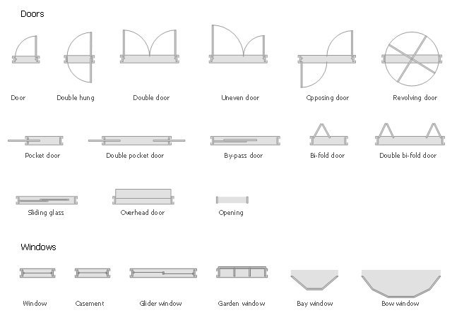
The design elements library Doors contains 69 symbols of doors.
The design elements library Windows contains 34 symbols of windows and casements.
"A door is an opening or closing structure used to block off an entrance, typically consisting of an interior side that faces the inside of a space and an exterior side that faces the outside of that space. While in some cases the interior side of a door may match its exterior side, in other cases there are sharp contrasts between the two sides, such as in the case of the vehicle door. In addition, doors typically consist of a panel that swings on hinges or that slides or spins inside of a space." [Door. Wikipedia]
"A window is an opening in a wall, door or vehicle that allows the passage of light and, if not closed or sealed, air and sound. Modern windows are usually glazed or covered in some other transparent or translucent material. Windows are held in place by frames. Many glazed windows may be opened, to allow ventilation, or closed, to exclude inclement weather." [Window. Wikipedia]
Use the shapes libraries Doors and Windows to create house plans, home plans, floor plan layouts and home designs using the ConceptDraw PRO diagramming and vector drawing software.
The vector stencils libraries Doors and Windows are provided by the Floor Plans solution from the Building Plans area of ConceptDraw Solution Park.
How To use House Electrical Plan Software


How To use Appliances Symbols for Building Plan


Interior Design Shipping and Receiving - Design Elements

The vector stencils library "Switches and relays" contains 58 symbols of electrical contacts, switches, relays, circuit breakers, selectors, connectors, disconnect devices, switching circuits, current regulators, and thermostats for electrical devices.
"In electrical engineering, a switch is an electrical component that can break an electrical circuit, interrupting the current or diverting it from one conductor to another.
The most familiar form of switch is a manually operated electromechanical device with one or more sets of electrical contacts, which are connected to external circuits. Each set of contacts can be in one of two states: either "closed" meaning the contacts are touching and electricity can flow between them, or "open", meaning the contacts are separated and the switch is nonconducting. The mechanism actuating the transition between these two states (open or closed) can be either a "toggle" (flip switch for continuous "on" or "off") or "momentary" (push-for "on" or push-for "off") type.
A switch may be directly manipulated by a human as a control signal to a system, such as a computer keyboard button, or to control power flow in a circuit, such as a light switch. Automatically operated switches can be used to control the motions of machines, for example, to indicate that a garage door has reached its full open position or that a machine tool is in a position to accept another workpiece. Switches may be operated by process variables such as pressure, temperature, flow, current, voltage, and force, acting as sensors in a process and used to automatically control a system. ... A switch that is operated by another electrical circuit is called a relay. Large switches may be remotely operated by a motor drive mechanism. Some switches are used to isolate electric power from a system, providing a visible point of isolation that can be padlocked if necessary to prevent accidental operation of a machine during maintenance, or to prevent electric shock." [Switch. Wikipedia]
"A relay is an electrically operated switch. Many relays use an electromagnet to mechanically operate a switch, but other operating principles are also used, such as solid-state relays. Relays are used where it is necessary to control a circuit by a low-power signal (with complete electrical isolation between control and controlled circuits), or where several circuits must be controlled by one signal. The first relays were used in long distance telegraph circuits as amplifiers: they repeated the signal coming in from one circuit and re-transmitted it on another circuit. Relays were used extensively in telephone exchanges and early computers to perform logical operations.
A type of relay that can handle the high power required to directly control an electric motor or other loads is called a contactor. Solid-state relays control power circuits with no moving parts, instead using a semiconductor device to perform switching. Relays with calibrated operating characteristics and sometimes multiple operating coils are used to protect electrical circuits from overload or faults; in modern electric power systems these functions are performed by digital instruments still called "protective relays"." [Relay. Wikipedia]
The shapes example "Design elements - Switches and relays" was drawn using the ConceptDraw PRO diagramming and vector drawing software extended with the Electrical Engineering solution from the Engineering area of ConceptDraw Solution Park.
Switch and relay symbols

The vector stencils library "Shipping and receiving" contains 18 symbols of industrial shipping and receiving equipment.
Use the design elements library "Shipping and receiving" to draw factory warehouse equipment layout plans, floor plans of shipping and receiving centers with equipment for hauling, transporting, and distributing manufactured goods, freight, cargo, and stock from plants and industrial facilities using the ConceptDraw PRO diagramming and vector drawing software.
"Freight transport, or shipping, is a key in the value chain in manufacturing.
While all modes of transport are used for cargo transport, there is high differentiation between the nature of the cargo transport, in which mode is chosen.
Logistics refers to the entire process of transferring products from producer to consumer, including storage, transport, transshipment, warehousing, material-handling and packaging, with associated exchange of information.
Containerization, with the standardization of ISO containers on all vehicles and at all ports, has revolutionized international and domestic trade, offering huge reduction in transshipment costs. Traditionally, all cargo had to be manually loaded and unloaded into the haul of any ship or car; containerization allows for automated handling and transfer between modes, and the standardized sizes allow for gains in economy of scale in vehicle operation." [Transport. Freight.
Wikipedia]
This shapes library "Shipping and receiving" is included in the Plant Layout Plans solution from the Building Plans area of ConceptDraw Solution Park.
Shipping and receiving symbols

Symbol for Pool Table for Floor Plans

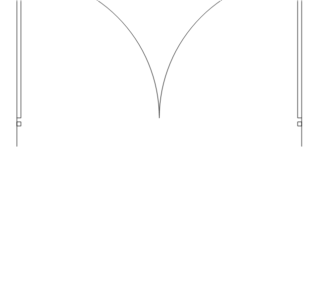
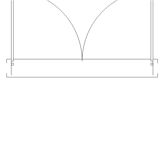
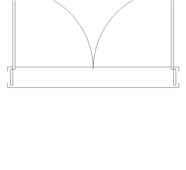
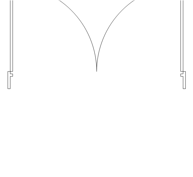
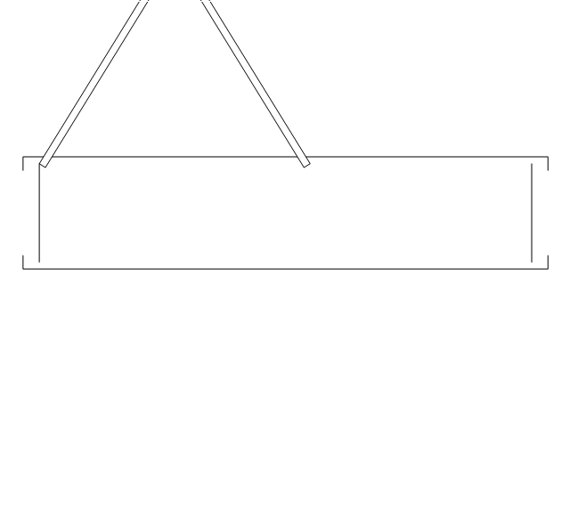
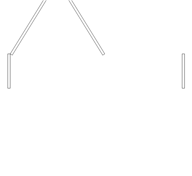
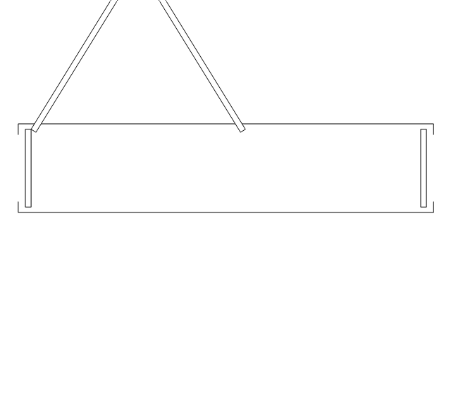
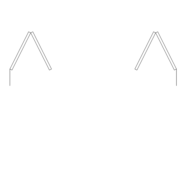
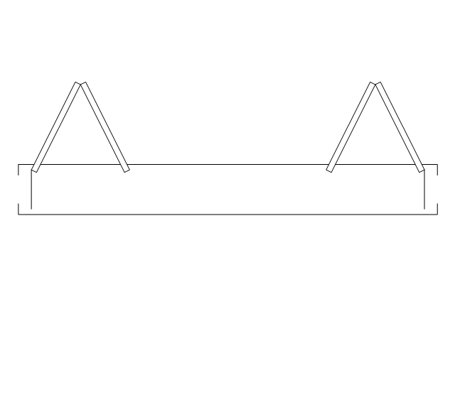
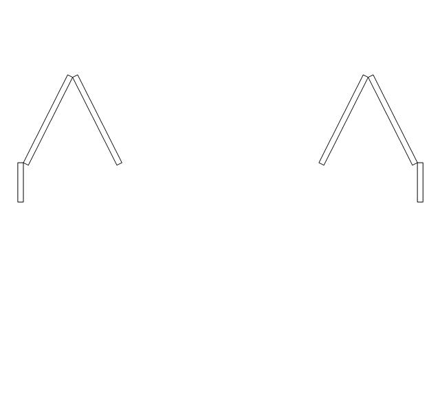
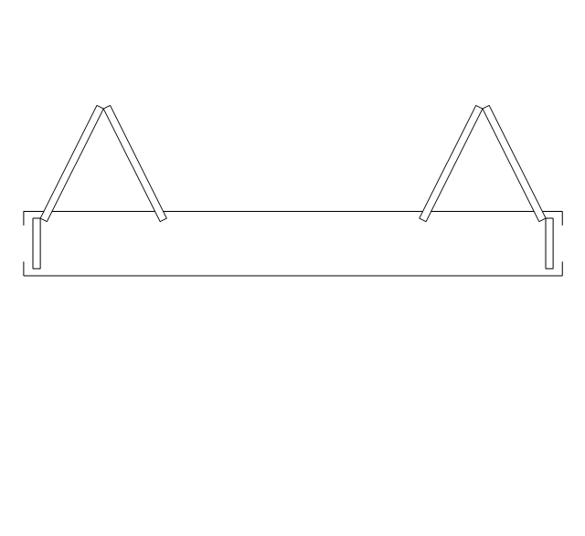
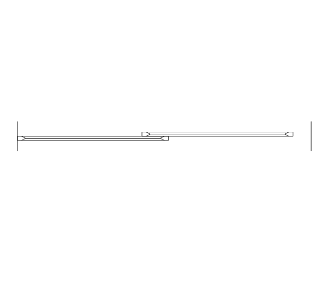
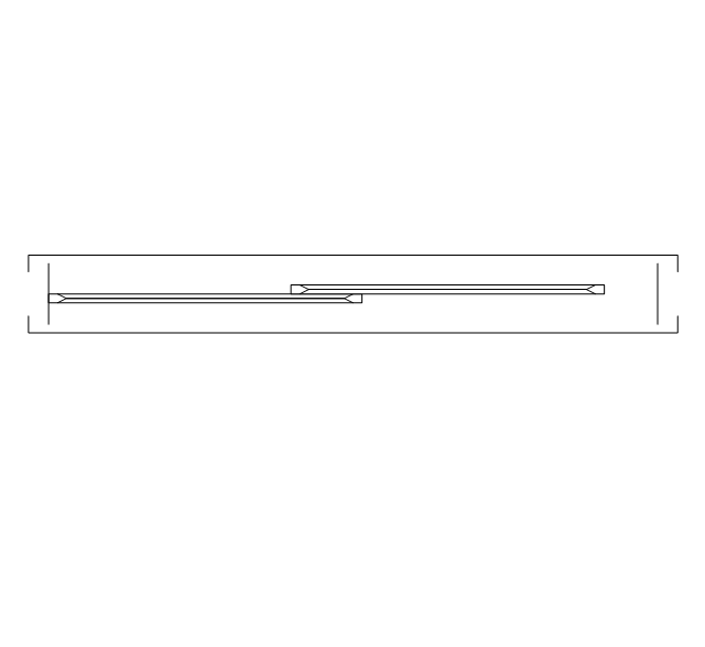
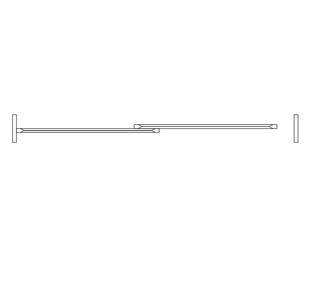
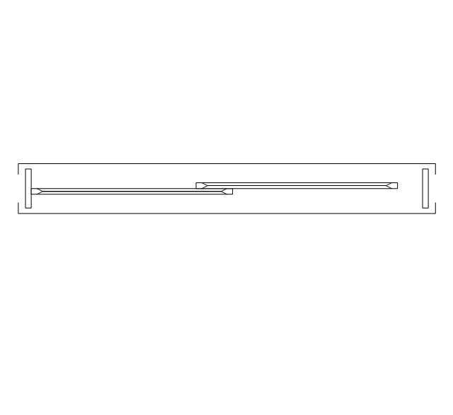
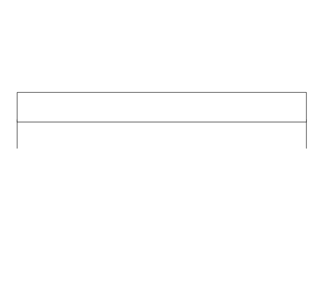
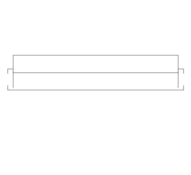
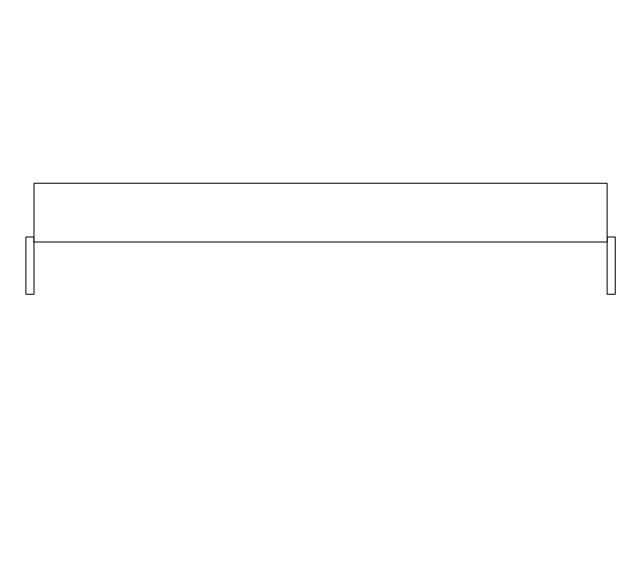
The vector stencils library "Doors" contains 69 shapes of doors. Use it for drawing floor plans in the ConceptDraw PRO diagramming and vector drawing software extended with the Floor Plans solution from the Building Plans area of ConceptDraw Solution Park.
Opening

Door

Door, threshold
Door, stop
Door, stop, threshold
Door, frame
Door, frame, threshold
Door, frame, stop

Door, frame, stop, threshold

Double hung
Double hung, threshold
Double hung, frame
Double hung, frame, threshold
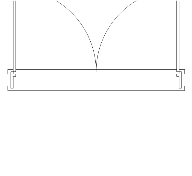
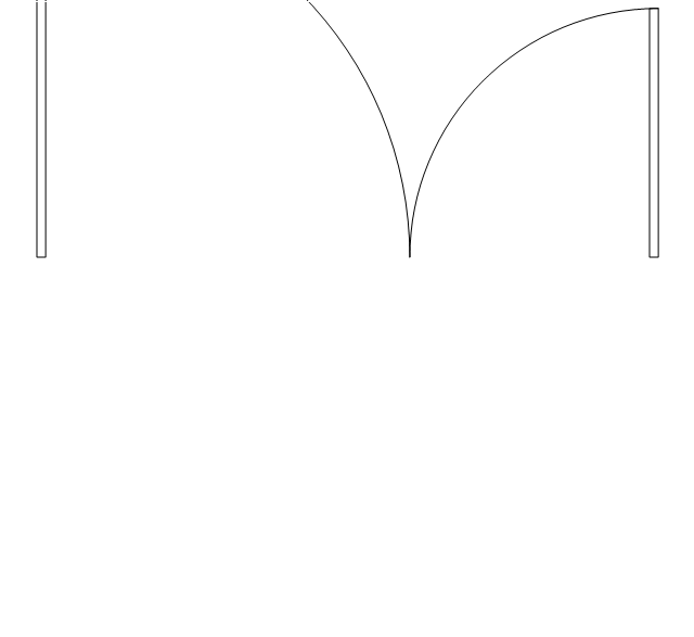
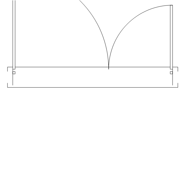
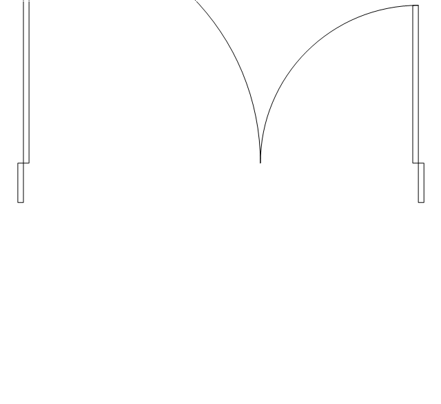
Double door
Double door, threshold
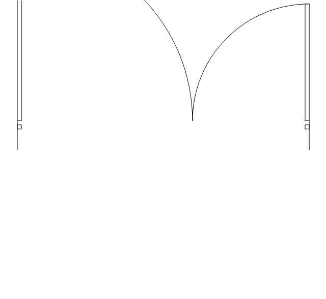
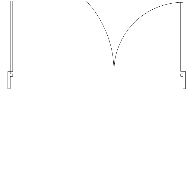
Double door, stop
Double door, stop, threshold
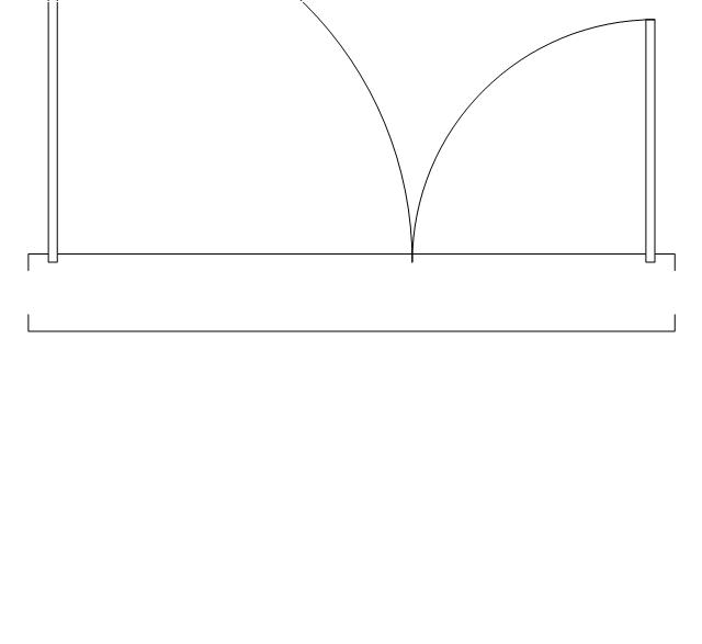
Double door, frame

Double door, frame, threshold
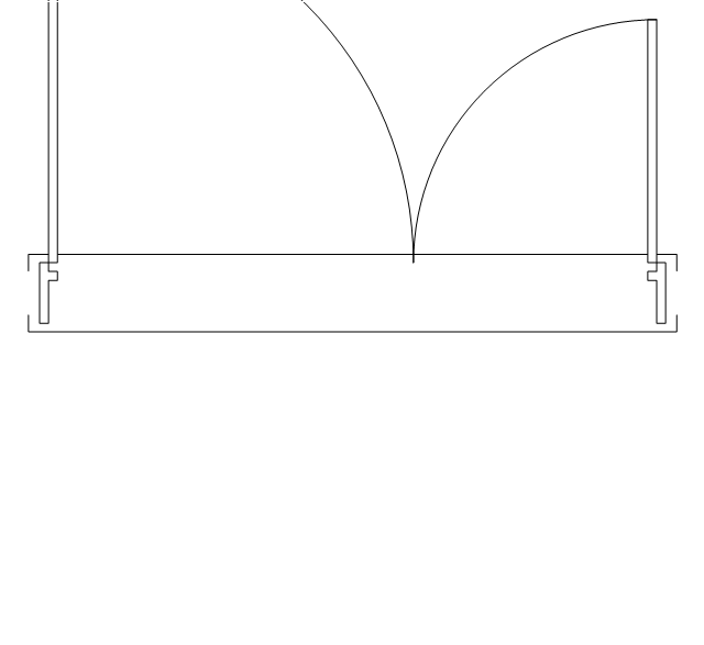
Double door, frame, stop
Double door, frame, stop, threshold
Uneven door
Uneven door, threshold
Uneven door, stop
Uneven door, stop, threshold
Uneven door, frame
Uneven door, frame, threshold

Uneven door, frame, stop
Uneven door, frame, stop, threshold
Opposing door

Opposing door, threshold

Opposing door, stop
Opposing door, stop, threshold
Opposing door, frame

Opposing door, frame, threshold

Opposing door, frame, stop
Opposing door, frame, stop, threshold
Revolving door
Revolving door, threshold
Revolving door, frame
Revolving door, frame, threshold
Pocket door
Pocket door, threshold
Pocket door, frame
Pocket door, frame, threshold
Dbl pocket door
Dbl pocket door, threshold
Dbl pocket door, frame
Dbl pocket door, frame, threshold
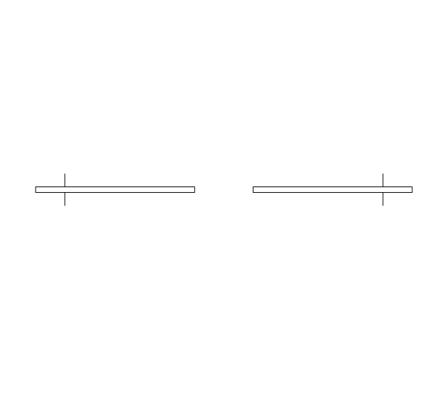
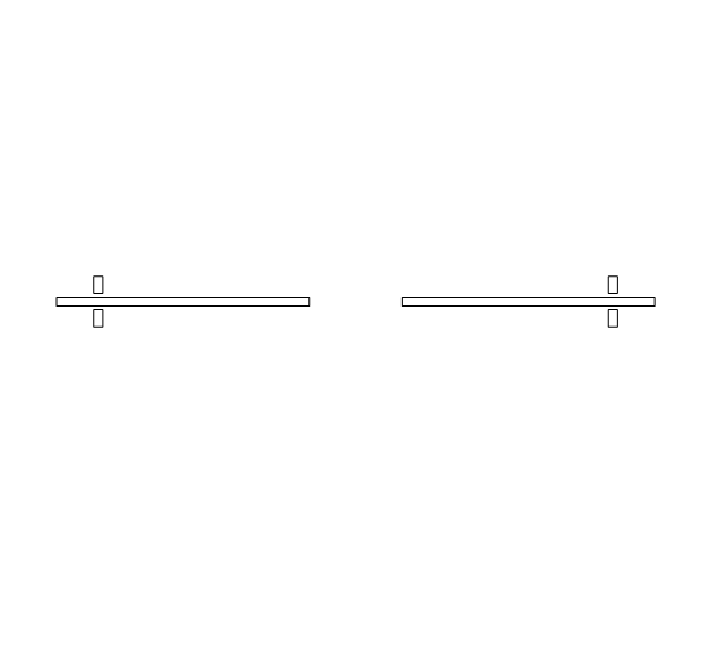
By-pass door
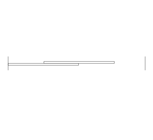
By-pass door, threshold

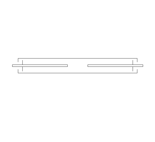
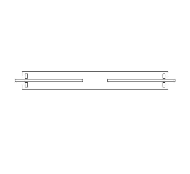
By-pass door, frame

By-pass door, frame, threshold

Bi-fold door
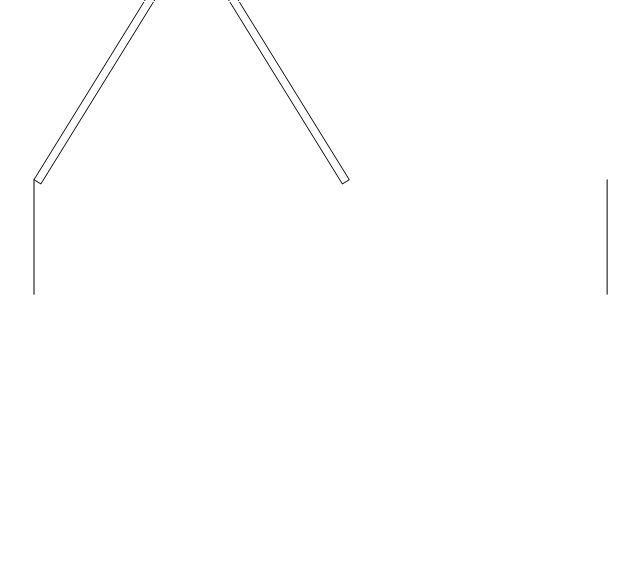
Bi-fold door, threshold
Bi-fold door, frame
Bi-fold door, frame, threshold
Double bi-fold door
Double bi-fold door, threshold
Double bi-fold door, frame
Double bi-fold door, frame, threshold
Sliding glass
Sliding glass, threshold
Sliding glass, frame
Sliding glass, frame, threshold
Overhead door
Overhead door, threshold
Overhead door, frame
Overhead door, frame, threshold
The vector stencils library "Switches" contains 25 symbols of electrical and light switches and breakers.
"In electrical engineering, a switch is an electrical component that can break an electrical circuit, interrupting the current or diverting it from one conductor to another.
The most familiar form of switch is a manually operated electromechanical device with one or more sets of electrical contacts, which are connected to external circuits.
A switch may be directly manipulated by a human as a control signal to a system, ... or to control power flow in a circuit, such as a light switch. Automatically operated switches can be used to control the motions of machines, for example, to indicate that a garage door has reached its full open position or that a machine tool is in a position to accept another workpiece. Switches may be operated by process variables such as pressure, temperature, flow, current, voltage, and force, acting as sensors in a process and used to automatically control a system. For example, a thermostat is a temperature-operated switch used to control a heating process. A switch that is operated by another electrical circuit is called a relay." [Switch. Wikipedia]
Use the design elements library "Switches" for drawing light switches layouts, electrical and telecommunication equipment floor plans for building design and construction using the ConceptDraw PRO diagramming and vector drawing software.
The shapes library "Switches" is included in the Electric and Telecom Plans solution from the Building Plans area of ConceptDraw Solution Park.
Electrical switch symbols

The vector stencils library "Electrical and telecom" contains 83 symbols of electrical and telecommunication equipment.
Use these shapes for drawing electrical and telecom system design floor plans, cabling layout schemes, and wiring diagrams in the ConceptDraw PRO diagramming and vector drawing software.
The vector stencils library "Electrical and telecom" is included in the Electric and Telecom Plans solution from the Building Plans area of ConceptDraw Solution Park.
Luminaire ceiling mount

Enclosed ceiling luminaire

Wall light

1-light bar

2-light bar

4-light bar

6-light bar

8-light bar

Down lighter

Outdoor lightning

Outdoor lightning, bollard

Batten fluorescent, 1 lamp

Batten fluorescent, 2 lamps

Batten fluorescent, 3 lamps

Batten fluorescent, 4 lamps

Surface Fluorescent Light

Modular fluorescent fitting

Modular fluorescent fitting, inverter

Modular fluorescent fitting 2

Pull-cord switch

Emergency light

Emergency light 2

Emergency sign

Switch

Switch, 1 pole

Switch, 2 pole

Switch, 2-way

Multi-switch

Switch, intermediate

Dimmer switch

Dimmer switch 2

Socket

Socket 2

Switched socket

Switched socket 2

Double socket

Double socket 2

Socket outlet

Telephone outlet

Telephone outlet 2

Stereo outlet

Television outlet

Service panel, surface

Service panel, inset

Thermostat

Ceiling fan

Hold open unit

Detector

Fire alarm

City Fire Alarm Station

Fire Alarm Station

Fire Alarm Bell

Fire Alarm Central Station

Automatic Fire Alarm Device

Main control

Ground

Doorbell

Push Button

Buzzer

Annunciator

Horn

Maid's Signal Plug

Signal Central Station

Doorbell Chime

Doorbell Transformer

Magnetic Door Hold

Intercom

Telephone Key System

Digital Satellite System

Inside Antenna

Outside Antenna

Electric Motors

Single Phase

Three of Poly Phase

Wall Mounted Electrical Junction Box for Hardware

Wall Mounted Telephone/Data Junction Box for Hardware

Card Reader Access System

Emergency Release Button

Motion Sensor

Electric Door Opener

Watchman's Station

Watchman's Central Station

Battery

The design elements library Walls, shell and structure contains 29 symbols of structural elements: walls, rooms, windows, doors, pillars.
Use the vector stencils library Walls, shell and structure to draw the floor plans and other architectural drawings, blueprints, home and building interior design, space layout plans, construction and house framing diagrams using the ConceptDraw PRO diagramming and vector drawing software.
"A wall is a horizontal structure, usually solid, that defines and sometimes protects an area. Most commonly, a wall delineates a building and supports its superstructure, separates space in buildings into sections, or protects or delineates a space in the open air. There are three principal types of structural walls: building walls, exterior boundary walls, and retaining walls.
Building walls have one main purpose: to support roofs and ceilings. Such walls most often have three or more separate components. In today's construction, a building wall will usually have the structural elements (such as 2×4 studs in a house wall), insulation, and finish elements or surface (such as drywall or panelling). In addition, the wall may house various types of electrical wiring or plumbing. Electrical outlets are usually mounted in walls.
Building walls frequently become works of art externally and internally, such as when featuring mosaic work or when murals are painted on them; or as design foci when they exhibit textures or painted finishes for effect.
In architecture and civil engineering, the term curtain wall refers to the facade of a building which is not load-bearing but functions as decoration, finish, front, face, or history preservation." [Wall. Wikipedia]
This shapes library Walls, shell and structure is provided by the Floor Plans solution from the Building Plans area of ConceptDraw Solution Park.

The vector stencils library "Switches" contains 25 symbols of electrical switches.
Use it for drawing electrical design floor and building plans, devices and equipment layouts in the ConceptDraw PRO diagramming and vector drawing software.
The vector stencils library "Switches" is included in the Electric and Telecom Plans solution from the Building Plans area of ConceptDraw Solution Park.
Single pole switch

Switch control

Dimmer switch

Dimmer switch 2

Double Pole Switch

Three-way switch

Four-way switch

Automatic door switch

Electrolier switch

Key operated switch

Switch and pilot lamp

Key operated switch with pilot light

Circuit breaker

Weatherproof circuit breaker

Momentary contact switch

Remote control switch

Weatherproof switch

Fused switch

Weatherproof fused switch

Switch with timer

Glow switch toggle

Horizontally mounted switch

Low voltage master switch

Low voltage switch

Single pole double throw switch

Home Remodeling Software. Home Plan Examples

- Symbol Of Double Hung Door
- Floor Plan Symbol For Slding Glass Doors
- Doors - Vector stencils library | Symbol Blueprint Glass
- Mechanical Door Symbol
- Doors - Vector stencils library | Symbol Of Revolving Door In ...
- Design elements - Doors and windows | Symbol for Pool Table for ...
- Architectural Symbol For Pocket Door
- Doors Symbol
- Door Orientation Symbol Architecture
- Doors - Vector stencils library | Appliances - Vector stencils library ...
- Door Symbol Used In Layout Diagram
- Symbol Of Various Type Of Door N Window
- Door Plan Symbol
- Door Symbols
- Casement Door Symbols
- Door Contact Sensor
- Door Diagram Symbol
- Door And Windows Vector Templates
- Window And Door Symbols
- Door Symbol In Architecture Blueprint