 Wireless Networks
The Wireless Networks Solution extends ConceptDraw DIAGRAM software with professional diagramming tools, set of wireless network diagram templates and samples, comprehensive library of wireless communications and WLAN objects to help network engineers and designers efficiently design and create Wireless network diagrams that illustrate wireless networks of any speed and complexity, and help to identify all required equipment for construction and updating wireless networks, and calculating their costs.
"A server is a system (software and suitable computer hardware) that responds to requests across a computer network to provide, or help to provide, a network service. Servers can be run on a dedicated computer, which is also often referred to as "the server", but many networked computers are capable of hosting servers. In many cases, a computer can provide several services and have several servers running.
Servers operate within a client-server architecture. Servers are computer programs running to serve the requests of other programs, the clients. Thus, the server performs some tasks on behalf of clients. The clients typically connect to the server through the network but may run on the same computer. In the context of Internet Protocol (IP) networking, a server is a program that operates as a socket listener.
Servers often provide essential services across a network, either to private users inside a large organization or to public users via the Internet. Typical computing servers are database server, file server, mail server, print server, web server, gaming server, application server, or some other kind of server.
Numerous systems use this client / server networking model including Web sites and email services. An alternative model, peer-to-peer networking enables all computers to act as either a server or client as needed." [Server (computing). Wikipedia]
The UML component diagram example "Start server" was created using the ConceptDraw PRO diagramming and vector drawing software extended with the Rapid UML solution from the Software Development area of ConceptDraw Solution Park.
UML component diagram

 Network Layout Floor Plans
Network Layout Floor Plans solution extends ConceptDraw DIAGRAM software functionality with powerful tools for quick and efficient documentation the network equipment and displaying its location on the professionally designed Network Layout Floor Plans. Never before creation of Network Layout Floor Plans, Network Communication Plans, Network Topologies Plans and Network Topology Maps was not so easy, convenient and fast as with predesigned templates, samples, examples and comprehensive set of vector design elements included to the Network Layout Floor Plans solution. All listed types of plans will be a good support for the future correct cabling and installation of network equipment.
Software development with ConceptDraw DIAGRAM

 Value Stream Mapping
Value stream mapping solution extends ConceptDraw DIAGRAM software with templates, samples and vector stencils for drawing the Value Stream Maps (VSM) in lean manufacturing practice.
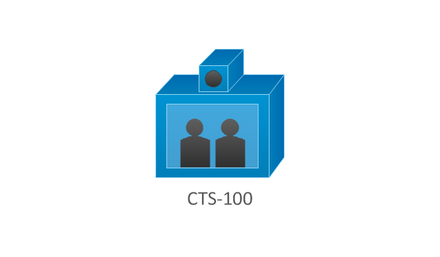
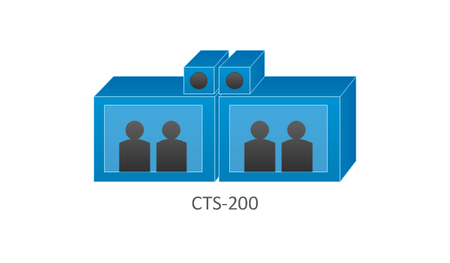
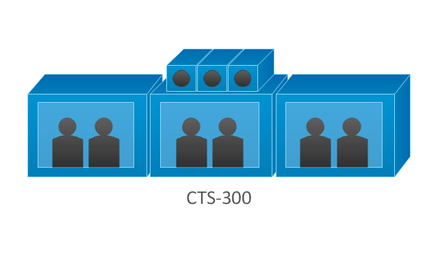
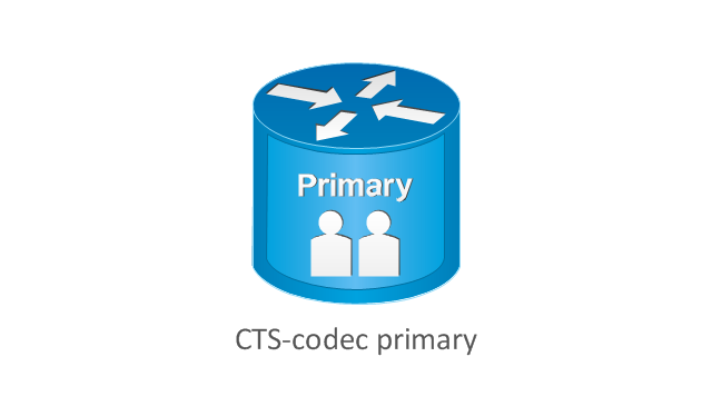
The vector stencils library "Cisco telepresence" contains 8 symbols of videoconference and telepresence equipment for drawing Cisco computer network diagrams.
"Videoconferencing is the conduct of a videoconference (also known as a video conference or videoteleconference) by a set of telecommunication technologies which allow two or more locations to communicate by simultaneous two-way video and audio transmissions. It has also been called 'visual collaboration' and is a type of groupware. ...
The core technology used in a videoconferencing system is digital compression of audio and video streams in real time. The hardware or software that performs compression is called a codec (coder/ decoder). Compression rates of up to 1:500 can be achieved. The resulting digital stream of 1s and 0s is subdivided into labeled packets, which are then transmitted through a digital network of some kind (usually ISDN or IP). The use of audio modems in the transmission line allow for the use of POTS, or the Plain Old Telephone System, in some low-speed applications, such as videotelephony, because they convert the digital pulses to/ from analog waves in the audio spectrum range.
The other components required for a videoconferencing system include:
(1) Video input : video camera or webcam.
(2) Video output: computer monitor, television or projector.
(3) Audio input: microphones, CD/ DVD player, cassette player, or any other source of PreAmp audio outlet.
(4) Audio output: usually loudspeakers associated with the display device or telephone.
(5) Data transfer: analog or digital telephone network, LAN or Internet.
(6) Computer: a data processing unit that ties together the other components, does the compressing and decompressing, and initiates and maintains the data linkage via the network." [Videoconferencing. Wikipedia]
The symbols example "Cisco telepresence - Vector stencils library" was created using the ConceptDraw PRO diagramming and vector drawing software extended with the Cisco Network Diagrams solution from the Computer and Networks area of ConceptDraw Solution Park.
www.conceptdraw.com/ solution-park/ computer-networks-cisco
CTS-100
CTS-200
CTS-300
CTS-codec primary
CTS-codec secondary
TP MCU
Cisco telepresence manager
MCU
 Office Layout Plans
Office layouts and office plans are a special category of building plans and are often an obligatory requirement for precise and correct construction, design and exploitation office premises and business buildings. Designers and architects strive to make office plans and office floor plans simple and accurate, but at the same time unique, elegant, creative, and even extraordinary to easily increase the effectiveness of the work while attracting a large number of clients.
ConceptDraw DIAGRAM Compatibility with MS Visio

- Computer and Networks Area | Network Layout Floor Plans ...
- Tools Required For Networking
- Logical network topology diagram | Network Topologies | Network ...
- Find out what amount and type of equipment is needed for your ...
- Wide area network (WAN) topology. Computer and Network Examples
- Network Layout | Cisco Network Design. Cisco icons, shapes ...
- Network Layout Floor Plans | Network Layout | Design elements ...
- Network Diagram Software Physical Network Diagram | Star ...
- ConceptDraw PRO Network Diagram Tool | Find out what amount ...
- Home area networks (HAN). Computer and Network Examples ...
- Computer Network Diagrams | Cisco Network Diagrams ...
- Rack Diagrams | Design Element: Rack Diagram for Network ...
- Metropolitan area networks (MAN). Computer and Network Examples
- Wide area network (WAN) topology. Computer and Network ...
- UML component diagram - Start server | Computer Network ...
- Computer network system design diagram | Network Diagramming ...
- UML component diagram - Start server | Server hardware - Rack ...
- Design Element: Rack Diagram for Network Diagrams | Rack ...
- Wireless Network Elements | Network Diagramming Software for ...
- Types Of Information Required Within The Information Pyramid