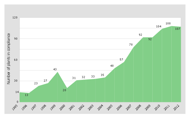
This area chart sample was redesigned from the picture "Outstanding trends of wastewater treatment plants" from the Washington State Department of Ecology website.
[ecy.wa.gov/ programs/ wq/ wastewater/ op_ cert/ kudos.html]
"Sewage treatment is the process of removing contaminants from wastewater and household sewage, both runoff (effluents), domestic, commercial and institutional. It includes physical, chemical, and biological processes to remove physical, chemical and biological contaminants. Its objective is to produce an environmentally safe fluid waste stream (or treated effluent) and a solid waste (or treated sludge) suitable for disposal or reuse (usually as farm fertilizer). Using advanced technology it is now possible to re-use sewage effluent for drinking water, although Singapore is the only country to implement such technology on a production scale in its production of NEWater." [Sewage treatment. Wikipedia]
The area graph example "Outstanding trends of wastewater treatment plants" was created using the ConceptDraw PRO diagramming and vector drawing software extended with the Area Charts solution from the Graphs and Charts area of ConceptDraw Solution Park.
www.conceptdraw.com/ solution-park/ charts-area
Area chart
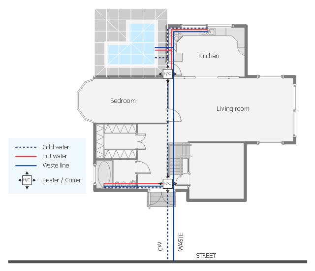
"Within industry, piping is a system of pipes used to convey fluids (liquids and gases) from one location to another. The engineering discipline of piping design studies the efficient transport of fluid. ...
Plumbing is a piping system with which most people are familiar, as it constitutes the form of fluid transportation that is used to provide potable water and fuels to their homes and businesses. Plumbing pipes also remove waste in the form of sewage, and allow venting of sewage gases to the outdoors. Fire sprinkler systems also use piping, and may transport nonpotable or potable water, or other fire-suppression fluids." [Piping. Wikipedia]
The house plumbing plan example was created using the ConceptDraw PRO diagramming and vector drawing software extended with the Plumbing and Piping Plans solution from the Building Plans area of ConceptDraw Solution Park.
House plumbing floor plan
The vector stencils library "Plumbing" contains 31 symbols of plumbing components and bathroom fixtures.
"Plumbing is the system of pipes, drains fittings, valves, valve assemblies, and devices installed in a building for the distribution of water for drinking, heating and washing, and the removal of waterborne wastes, and the skilled trade of working with pipes, tubing and plumbing fixtures in such systems. A plumber is someone who installs or repairs piping systems, plumbing fixtures and equipment such as water heaters and backflow preventers. The plumbing industry is a basic and substantial part of every developed economy due to the need for clean water, and sanitary collection and transport of wastes.
Plumbing is usually distinguished from water supply and sewage systems, in that a plumbing system serves one building, while water and sewage systems serve a group of buildings." [Plumbing. Wikipedia]
Use the design elements library "Plumbing" for drawing plumbing and piping plans, schematic diagrams and blueprints of waste water disposal systems, and hot and cold water supply systems using the ConceptDraw PRO diagramming and vector drawing software.
The shapes library "Plumbing" is included in the Plumbing and Piping Plans solution from the Building Plans area of ConceptDraw Solution Park.
Plumbing symbols

The vector stencils library "Valves and fittings" contains 104 symbols of valve components.
Use these icons for drawing industrial piping systems; process, vacuum, and fluids piping; hydraulics piping; air and gas piping; materials distribution; and liquid transfer systems.
"A valve is a device that regulates, directs or controls the flow of a fluid (gases, liquids, fluidized solids, or slurries) by opening, closing, or partially obstructing various passageways. Valves are technically valves fittings, but are usually discussed as a separate category. In an open valve, fluid flows in a direction from higher pressure to lower pressure.
The simplest, and very ancient, valve is simply a freely hinged flap which drops to obstruct fluid (gas or liquid) flow in one direction, but is pushed open by flow in the opposite direction. This is called a check valve, as it prevents or "checks" the flow in one direction. ...
Valves are found in virtually every industrial process, including water & sewage processing, mining, power generation, processing of oil, gas & petroleum, food manufacturing, chemical & plastic manufacturing and many other fields. ...
Valves may be operated manually, either by a handle, lever, pedal or wheel. Valves may also be automatic, driven by changes in pressure, temperature, or flow. These changes may act upon a diaphragm or a piston which in turn activates the valve, examples of this type of valve found commonly are safety valves fitted to hot water systems or boilers.
More complex control systems using valves requiring automatic control based on an external input (i.e., regulating flow through a pipe to a changing set point) require an actuator. An actuator will stroke the valve depending on its input and set-up, allowing the valve to be positioned accurately, and allowing control over a variety of requirements." [Valve. Wikipedia]
The example "Design elements - Valves and fittings" was created using the ConceptDraw PRO diagramming and vector drawing software extended with the Chemical and Process Engineering solution from the Engineering area of ConceptDraw Solution Park.
www.conceptdraw.com/ solution-park/ engineering-chemical-process
Valves and fittings symbols

- Outstanding trends of wastewater treatment plants | Sewage Treatment
- Building Drawing Software for Designing Plumbing | Interior Design ...
- Building Drawing Software for Designing Plumbing | Interior Design ...
- Building Drawing Software for Designing Plumbing | Design ...
- Interior Design Plumbing - Design Elements ... - Conceptdraw.com
- Design elements - Valves | Interior Design Piping Plan - Design ...
- Design elements - Pipes (part 1) - Conceptdraw.com
- Design elements - Plumbing | Interior Design Plumbing - Design ...
- Building Drawing Software for Design Piping Plan
- Interior Design Plumbing - Design Elements | Design elements ...
- Building Drawing Design Element: Plumbing
- Interior Design Plumbing - Design Elements | Building Drawing ...
- Building Drawing Design Element: Plumbing | Interior Design ...
- Design elements - Bathroom | Interior Design Plumbing - Design ...
- Design elements - Appliances | House plumbing plan | Built In Oven
- House plumbing plan | Flat design floor plan | Design elements ...
- Step Area Graph
- Design elements - Valves and fittings | Design elements - Pipes (part ...
- Interior Design Piping Plan - Design Elements | Design elements ...
- Design elements - Bathroom | Design elements - Kitchen and dining ...