This IDEF3 diagram example was redesigned from the Wikimedia Commons file: 6-4 Example IDEF3 Object State Transition Schematic.jpg.
[commons.wikimedia.org/ wiki/ File:6-4_ Example_ IDEF3_ Object_ State_ Transition_ Schematic.jpg]
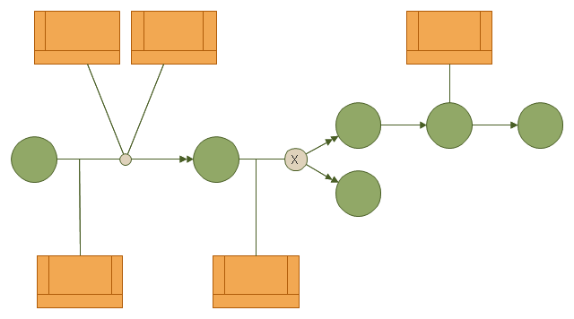
"Quick Reading of IDEF3 Process Descriptions: An Example.
An example approach for reading a schematic is described in the following steps. This outline for reading a schematic would be repeated, with few modifications, for all decompositions, whether found in a Process Schematic or an Object Schematic. In general, decompositions are read after the parent schematic has been read and understood.
The Big Picture.
A crucial step in the description-reading process is to understand the big picture
relevant to the real-life situation described. This big picture can be gained by reading and understanding the statement of purpose, statement of scope, objective of the scenario being described, and viewpoint of the IDEF3 Process Description. ...
Scan the Schematic.
Readers should become familiar with the scenario by scanning the schematic from left to right. This involves becoming familiar with the individual elements (e.g., UOBs, links, and junctions) displayed in the schematic. This is not an in-depth study of the schematic; rather, it provides readers with a general impression of the process being described and an overall understanding of the logic flow in the scenario.
Understand the Description.
In this step, readers gain a detailed understanding of the schematic associated with a scenario, object, or a decomposition of a schematic element. This is the part of the communication process that is most individualized and requires the most time. It is helpful to partition the schematic into understandable pieces." [IDEF3 Process Description Capture Method Report AL-TR-1995-XXXX. idef.com/ pdf/ Idef3_ fn.pdf]
The diagram sample "IDEF3 object state transition schematic" was created using the ConceptDraw PRO diagramming and vector drawing software extended with the solution "IDEF Business Process Diagrams" from the area "Business Processes" of ConceptDraw Solution Park.
[commons.wikimedia.org/ wiki/ File:6-4_ Example_ IDEF3_ Object_ State_ Transition_ Schematic.jpg]
"Quick Reading of IDEF3 Process Descriptions: An Example.
An example approach for reading a schematic is described in the following steps. This outline for reading a schematic would be repeated, with few modifications, for all decompositions, whether found in a Process Schematic or an Object Schematic. In general, decompositions are read after the parent schematic has been read and understood.
The Big Picture.
A crucial step in the description-reading process is to understand the big picture
relevant to the real-life situation described. This big picture can be gained by reading and understanding the statement of purpose, statement of scope, objective of the scenario being described, and viewpoint of the IDEF3 Process Description. ...
Scan the Schematic.
Readers should become familiar with the scenario by scanning the schematic from left to right. This involves becoming familiar with the individual elements (e.g., UOBs, links, and junctions) displayed in the schematic. This is not an in-depth study of the schematic; rather, it provides readers with a general impression of the process being described and an overall understanding of the logic flow in the scenario.
Understand the Description.
In this step, readers gain a detailed understanding of the schematic associated with a scenario, object, or a decomposition of a schematic element. This is the part of the communication process that is most individualized and requires the most time. It is helpful to partition the schematic into understandable pieces." [IDEF3 Process Description Capture Method Report AL-TR-1995-XXXX. idef.com/ pdf/ Idef3_ fn.pdf]
The diagram sample "IDEF3 object state transition schematic" was created using the ConceptDraw PRO diagramming and vector drawing software extended with the solution "IDEF Business Process Diagrams" from the area "Business Processes" of ConceptDraw Solution Park.
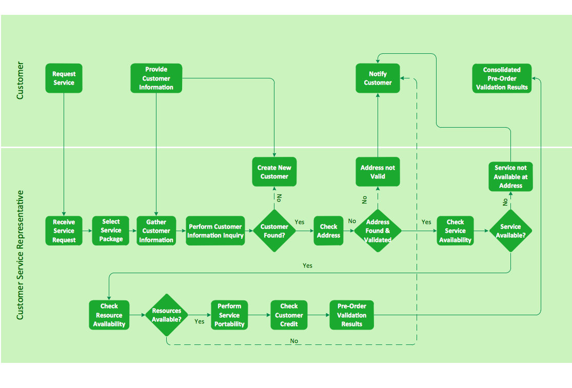
IDEF3 business process diagram
Cross-functional flowchart landscape, U.S. units
The cycle diagram sample was created on the base of the figure illustrating the webpage "2. POLICY & STRATEGY" of "Scottish Police College Primary Inspection 2006: A Report by Her Majesty's Inspectorate of Constabulary" from the Scottish Government website.
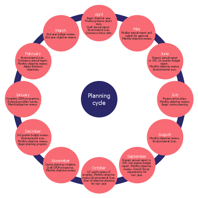
"Strategic Planning.
2.1 The planning process for the College currently follows a structured approach, starting in April and extending through the financial year. The planning cycle is illustrated in figure 2. ...
2.2 The College recognises the need to consult with its customers and stakeholders in the process of setting objectives and directing the training programme. The planning cycle to date refers to force visits, environmental scanning, the course planning process which involves consultation with all forces and other common police services, as well as to a survey of external providers.
2.3 The information from consultation feeds into an EFQM framework from which the College has identified four key policies, namely:
(1) developing and delivering quality training;
(2) developing our people through lifelong learning;
(3) continuous improvement of our service; and
(4) embracing the changing environment.
2.4 The objectives set at divisional level are designed to contribute to delivering these policies. HMIC found that whilst the selected objectives were presented in line with the structure, not all could be considered to meet SMART (Specific, Measurable, Achievable, Relevant and Timed) criteria. This failure indicates that while the process appears suitably structured to deliver a robust result, some of those involved could perhaps have a better understanding of the process." [scotland.gov.uk/ Publications/ 2007/ 02/ 15134652/ 8]
The cycle diagram example "Strategic planning" was created using the ConceptDraw PRO diagramming and vector drawing software extended with the Target and Circular Diagrams solution from the Marketing area of ConceptDraw Solution Park.
www.conceptdraw.com/ solution-park/ marketing-target-and-circular-diagrams
Cycle diagram
Bubble diagrams in Landscape Design with ConceptDraw DIAGRAM

ConceptDraw Arrows10 Technology
ConceptDraw Arrows10 Technology

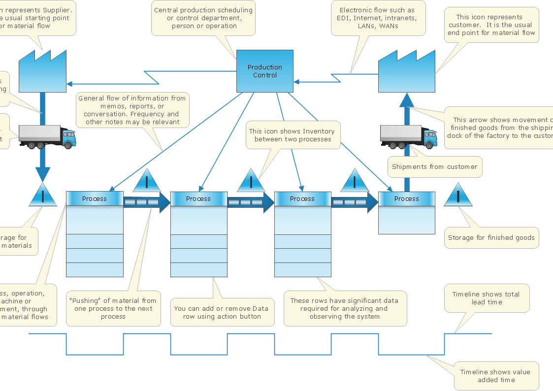
- Data flow diagram (DFD)
- Project planning process - Flowchart | Auditing Process . Audit ...
- Data Flow Diagram Symbols. DFD Library
- Process Flowchart | UML Diagram | Data Flow Diagrams | Diagrams
- Process Flowchart | IDEF3 object state transition schematic | IDEF ...
- Basic Flowchart Symbols and Meaning | Process Flowchart ...
- Flow chart Example. Warehouse Flowchart | Process Engineering ...
- BPR Diagram . Business Process Reengineering Example | Strategic ...
- Flow Chart Scanning Photographs To Digital
- Data Flow Diagram Symbols. DFD Library | Basic Flowchart ...
- Invoice payment process - Flowchart | Accounting Flowchart ...
- BPR Diagram . Business Process Reengineering Example | BPM life ...
- What is the Accounting Cycle? | Process Flowchart | Best Value ...
- Diagram Illustrating The Strategic Planning Process
- Marketing mix - Wheel diagram
- Process Flowchart | Types of Flowchart - Overview | IDEF3 object ...
- Successful Strategic Plan | Strategic planning - Cycle diagram ...
- IDEF3 Standard | How to create an IDEF3 diagram using ...
- Block diagram - Planning process | Project planning process ...
- Water cycle diagram | Strategic planning - Cycle diagram ...