The vector stencils library "HVAC ductwork" contains 55 duct and vent symbols of HVAC mechanical components. Use it for drawing HVAC ductwork system diagrams, heating, ventilation, air conditioning, refrigeration, automated building control, and environmental control design in the ConceptDraw PRO diagramming and vector drawing software extended with the HVAC Plans solution from the Building Plans area of ConceptDraw Solution Park.
Rect. duct, closed ends

Rect. duct, open 1 end

Rect. duct, open both ends

Circ. duct, closed ends

Circ. duct, open 1 end

Circ. duct, open both ends

Branch duct, rectangular

Branch duct, circular

Variable bend

Miter bend

Y junction

3 way junction

Junction 1

Beveled junction, rect. duct, rect. branch

Beveled junction, rect. duct, circ. branch

Beveled junction, circ. duct, rect. branch

Beveled junction, circ. duct, circ. branch

Transition, rect. to rect.

Transition, rect. to circ.

Transition, circ. to rect.

Transition, circ. to circ.

Offset transition, rect. to rect.

Offset transition, rect. to circ.

Offset transition, circ. to rect.

Offset transition, circ. to circ.

Flexible connection, rect. duct

Flexible connection, circ. duct

Flexible connection 2, rect. duct

Flexible connection 2, circ. duct

Supply, rect. duct toward

Supply, rect. duct away

Supply, rect. duct, elbow away

Supply, circ. duct toward

Supply, circ. duct away

Supply, circ. duct, elbow away

Return, rect. duct toward

Return, rect. duct away

Return, rect. duct, elbow away

Return, circ. duct toward

Return, circ. duct away

Return, circ. duct, elbow away

Sliding damper, rect. duct

Sliding damper, circ. duct

Damper, ACD

Damper, BD

Damper, FD/AD

Damper, MD

Damper, SD/AD

Vert. duct, rect. duct toward

Vert. duct, rect. duct away

Vert. duct, rect. duct, elbow away

Vert. duct, circ. duct toward

Vert. duct, circ. duct away

Vert. duct, circ. duct, elbow away

VAV box

The vector stencils library "HVAC ductwork" contains 55 duct and vent symbols of HVAC mechanical components. Use it for drawing HVAC ductwork system diagrams, heating, ventilation, air conditioning, refrigeration, automated building control, and environmental control design in the ConceptDraw PRO diagramming and vector drawing software extended with the HVAC Plans solution from the Building Plans area of ConceptDraw Solution Park.
Rect. duct, closed ends
Rect. duct, open 1 end
Rect. duct, open both ends
Circ. duct, closed ends
Circ. duct, open 1 end
Circ. duct, open both ends
Branch duct, rectangular
Branch duct, circular
Variable bend
Miter bend
Y junction
3 way junction
Junction 1
Beveled junction, rect. duct, rect. branch
Beveled junction, rect. duct, circ. branch
Beveled junction, circ. duct, rect. branch
Beveled junction, circ. duct, circ. branch
Transition, rect. to rect.
Transition, rect. to circ.
Transition, circ. to rect.
Transition, circ. to circ.
Offset transition, rect. to rect.
Offset transition, rect. to circ.
Offset transition, circ. to rect.
Offset transition, circ. to circ.
Flexible connection, rect. duct
Flexible connection, circ. duct
Flexible connection 2, rect. duct
Flexible connection 2, circ. duct
Supply, rect. duct toward
Supply, rect. duct away
Supply, rect. duct, elbow away
Supply, circ. duct toward
Supply, circ. duct away
Supply, circ. duct, elbow away
Return, rect. duct toward
Return, rect. duct away
Return, rect. duct, elbow away
Return, circ. duct toward
Return, circ. duct away
Return, circ. duct, elbow away
Sliding damper, rect. duct
Sliding damper, circ. duct
Damper, ACD
Damper, BD
Damper, FD/AD
Damper, MD
Damper, SD/AD
Vert. duct, rect. duct toward
Vert. duct, rect. duct away
Vert. duct, rect. duct, elbow away
Vert. duct, circ. duct toward
Vert. duct, circ. duct away
Vert. duct, circ. duct, elbow away
VAV box
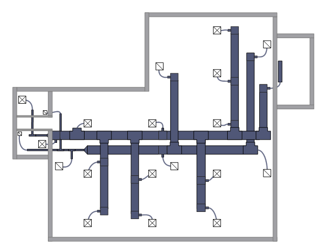
This HVAC floor plan sample shows the ventilation duct system layout.
"Ducts are used in heating, ventilation, and air conditioning (HVAC) to deliver and remove air. The needed airflows include, for example, supply air, return air, and exhaust air. Ducts commonly also deliver ventilation air as part of the supply air. As such, air ducts are one method of ensuring acceptable indoor air quality as well as thermal comfort.
A duct system is also called ductwork. Planning (laying out), sizing, optimizing, detailing, and finding the pressure losses through a duct system is called duct design." [Duct (flow). Wikipedia]
The HVAC floor plan example "Ductwork layout" was created using the ConceptDraw PRO diagramming and vector drawing software extended with the HVAC Plans solution from the Building Plans area of ConceptDraw Solution Park.
HVAC floor plan

The vector stencils library "HVAC ductwork" contains 55 ducts, vents and HVAC mechanical components symbols.
Use the design elements library "HVAC ductwork" for drawing the HVAC ductwork system diagrams, heating, ventilation, air conditioning, refrigeration, automated building control and environmental control system layout floor plans.
"Ducts are used in heating, ventilation, and air conditioning (HVAC) to deliver and remove air. These needed airflows include, for example, supply air, return air, and exhaust air. Ducts also deliver, most commonly as part of the supply air, ventilation air. As such, air ducts are one method of ensuring acceptable indoor air quality as well as thermal comfort.
A duct system is often called ductwork. Planning ('laying out'), sizing, optimizing, detailing, and finding the pressure losses through a duct system is called duct design." [Duct (HVAC). Wikipedia]
The shapes library "HVAC ductwork" is included in the HVAC Plans solution from the Building Plans area of ConceptDraw Solution Park.
HVAC ductwork symbols

This HVAC plan sample shows the air handler layout on the floor plan.
"An air handler, or air handling unit (often abbreviated to AHU), is a device used to condition and circulate air as part of a heating, ventilating, and air-conditioning (HVAC) system. An air handler is usually a large metal box containing a blower, heating or cooling elements, filter racks or chambers, sound attenuators, and dampers. Air handlers usually connect to a ductwork ventilation system that distributes the conditioned air through the building and returns it to the AHU. Sometimes AHUs discharge (supply) and admit (return) air directly to and from the space served without ductwork.
Small air handlers, for local use, are called terminal units, and may only include an air filter, coil, and blower; these simple terminal units are called blower coils or fan coil units. A larger air handler that conditions 100% outside air, and no recirculated air, is known as a makeup air unit (MAU). An air handler designed for outdoor use, typically on roofs, is known as a packaged unit (PU) or rooftop unit (RTU)." [Air handler. Wikipedia]
The floor plan example "Air handler - HVAC plan" was created using the ConceptDraw PRO diagramming and vector drawing software extended with the HVAC Plans solution from the Building Plans area of ConceptDraw Solution Park.
Floor plan

This HVAC floor plan sample depicts the layout of ventilation system air supply and exhaust ductwork.
"Ventilation is the process of changing or replacing air in any space to control temperature or remove any combination of moisture, odors, smoke, heat, dust, airborne bacteria, or carbon dioxide, and to replenish oxygen. Ventilation includes both the exchange of air with the outside as well as circulation of air within the building. It is one of the most important factors for maintaining acceptable indoor air quality in buildings. Methods for ventilating a building may be divided into mechanical/ forced and natural types." [HVAC. Wikipedia]
The HVAC floor plan example "Ventilation duct system" was created using the ConceptDraw PRO diagramming and vector drawing software extended with the HVAC Plans solution from the Building Plans area of ConceptDraw Solution Park.
HVAC floor plan
 HVAC Plans
Use HVAC Plans solution to create professional, clear and vivid HVAC-systems design plans, which represent effectively your HVAC marketing plan ideas, develop plans for modern ventilation units, central air heaters, to display the refrigeration systems for automated buildings control, environmental control, and energy systems.
- Return Air Vent Symbol
- Hvac Supply Return Drawing Symbols
- Design elements - HVAC ductwork
- Ductwork layout | Design elements - HVAC ductwork | HVAC control ...
- Return , rect. duct toward
- Design elements - HVAC ductwork | Interior Design Registers, Drills ...
- Ductwork layout | Design elements - HVAC ductwork | Building ...
- How to Create a HVAC Plan | HVAC Plans | Ductwork layout | Hvac ...
- Ductwork layout | HVAC Plans | Design elements - HVAC ductwork ...
- Ductwork layout | Design elements - HVAC ductwork | HVAC ...