The vector stencils library "Transistors" contains 30 symbols of transistors drawing electronic schematics and circuit diagrams.
"A transistor is a semiconductor device used to amplify and switch electronic signals and electrical power. It is composed of semiconductor material with at least three terminals for connection to an external circuit. A voltage or current applied to one pair of the transistor's terminals changes the current through another pair of terminals. Because the controlled (output) power can be higher than the controlling (input) power, a transistor can amplify a signal. Today, some transistors are packaged individually, but many more are found embedded in integrated circuits.
The transistor is the fundamental building block of modern electronic devices, and is ubiquitous in modern electronic systems. ...
Transistors are categorized by:
(1) Semiconductor material...: the metalloids germanium ... and silicon ... in amorphous, polycrystalline and monocrystalline form; the compounds gallium arsenide ... and silicon carbide ..., the alloy silicon-germanium ..., the allotrope of carbon graphene ...
(2) Structure: BJT, JFET, IGFET (MOSFET), insulated-gate bipolar transistor, "other types"
(3) Electrical polarity (positive and negative): n–p–n, p–n–p (BJTs); n-channel, p-channel (FETs)
(4) Maximum power rating: low, medium, high
(5) Maximum operating frequency: low, medium, high, radio (RF), microwave frequency...
(6) Application: switch, general purpose, audio, high voltage, super-beta, matched pair
(7) Physical packaging: through-hole metal, through-hole plastic, surface mount, ball grid array, power modules...
(8) Amplification factor..." [Transistor. Wikipedia]
The shapes example "Design elements - Transistors" was drawn using the ConceptDraw PRO diagramming and vector drawing software extended with the Electrical Engineering solution from the Engineering area of ConceptDraw Solution Park.
Transistor symbols

Near field communication (NFC). Computer and Network Examples


The vector stencils library "Design elements - Electron tubes" contains 36 element symbols of electron tubes.
Use it for drawing electrical schematics and electronic circuit diagrams.
"One classification of vacuum tubes is by the number of active electrodes, (neglecting the filament or heater). A device with two active elements is a diode, usually used for rectification. Devices with three elements are triodes used for amplification and switching. Additional electrodes create tetrodes, pentodes, and so forth, which have multiple additional functions made possible by the additional controllable electrodes.
Other classifications are:
(1) by frequency range (audio, radio, VHF, UHF, microwave),
(2) by power rating (small-signal, audio power, high-power radio transmitting),
(3) by design (e.g., sharp- versus remote-cutoff in some pentodes),
(4) by application (receiving tubes, transmitting tubes, amplifying or switching, rectification, mixing),
(5) special qualities (long life, very low microphonic and low noise audio amplification, and so on).
Multiple classifications may apply to a device; for example similar dual triodes can be used for audio preamplification and as flip-flops in computers, although linearity is important in the former case and long life in the latter.
Tubes have different functions, such as cathode ray tubes which create a beam of electrons for display purposes (such as the television picture tube) in addition to more specialized functions such as electron microscopy and electron beam lithography. X-ray tubes are also vacuum tubes. Phototubes and photomultipliers rely on electron flow through a vacuum, though in those cases electron emission from the cathode depends on energy from photons rather than thermionic emission." [Vacuum tube. Wikipedia]
The symbols example "Design elements - Electron tubes" was drawn using the ConceptDraw PRO diagramming and vector drawing software extended with the Electrical Engineering solution from the Engineering area of ConceptDraw Solution Park.
Vacuum tubes

Daisy Chain Network Topology

Network Glossary Definition

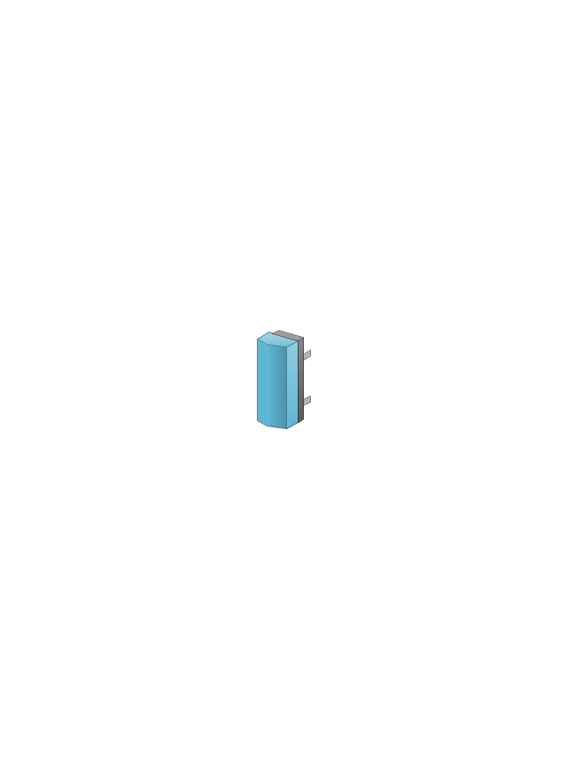
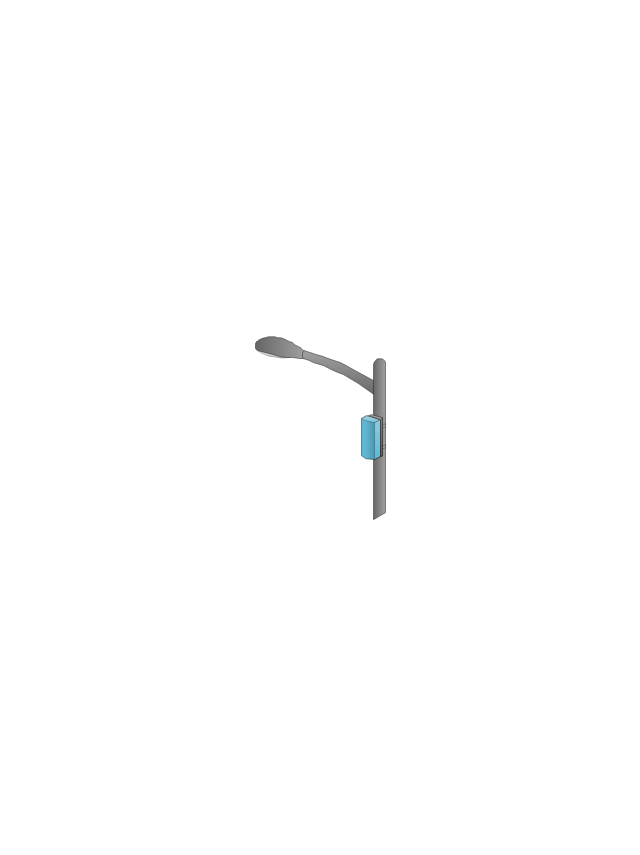
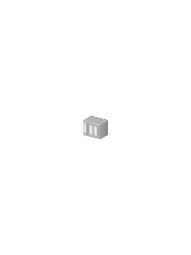
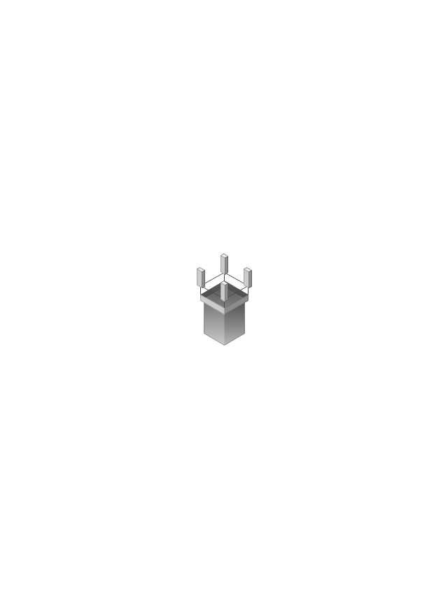
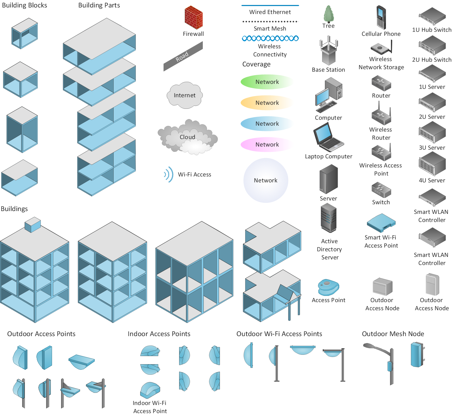
The vector stencils library "Wireless networks" contains 82 icon symbols for drawing wireless computer network diagrams and equipment layout plans.
"A wireless network is any type of computer network that uses wireless data connections for connecting network nodes.
Wireless networking is a method by which homes, telecommunications networks and enterprise (business) installations avoid the costly process of introducing cables into a building, or as a connection between various equipment locations.
Wireless telecommunications networks are generally implemented and administered using radio communication. This implementation takes place at the physical level (layer) of the OSI model network structure.
Examples of wireless networks include cell phone networks, Wi-Fi local networks and terrestrial microwave networks." [Wireless network. Wikipedia]
The clip art example "Wireless networks - Vector stencils library" was created using the ConceptDraw PRO diagramming and vector drawing software extended with the Wireless Networks solution from the Computer and Networks area of ConceptDraw Solution Park.
www.conceptdraw.com/ solution-park/ wireless-networks
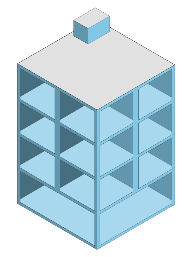
Building 1
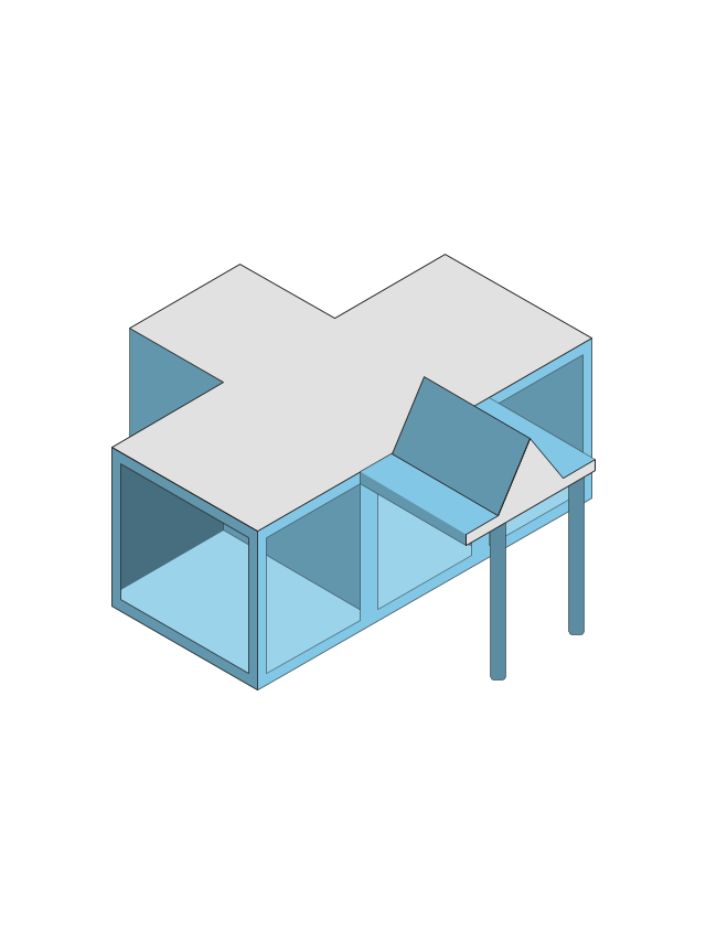
Building 4
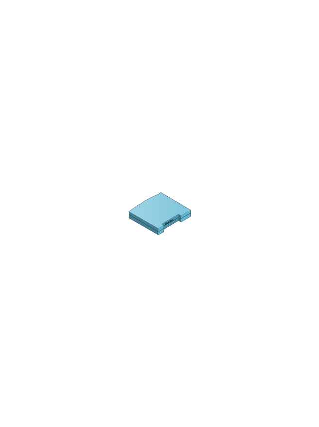
Coverage (Blue)
-wireless-networks---vector-stencils-library.png--diagram-flowchart-example.png)
Wireless Connectivity

Network Cloud

Cloud
Wi-Fi Access

Tree

Computer
Laptop Computer
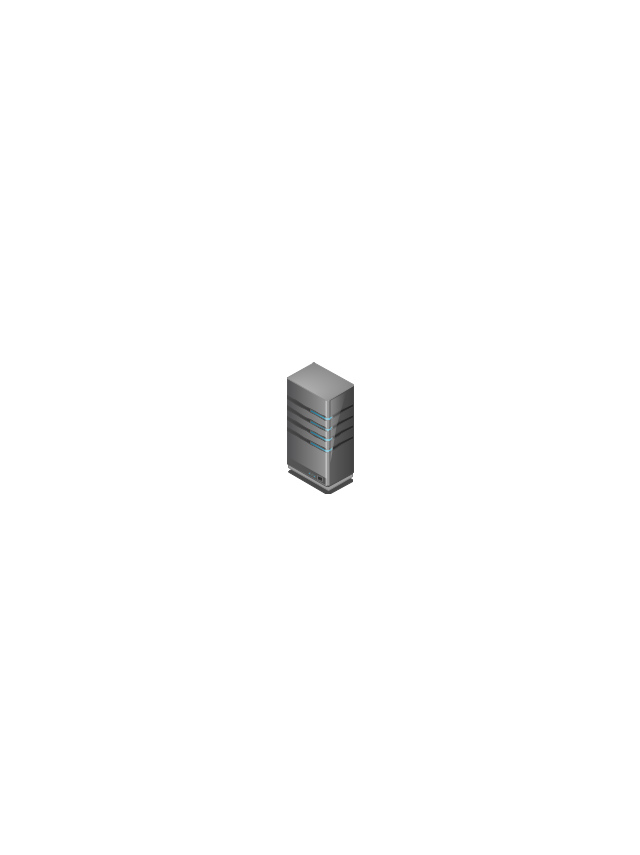
Server
Wireless Network Storage

Router
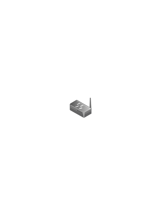
Wireless Router
Switch
Wireless Access Point
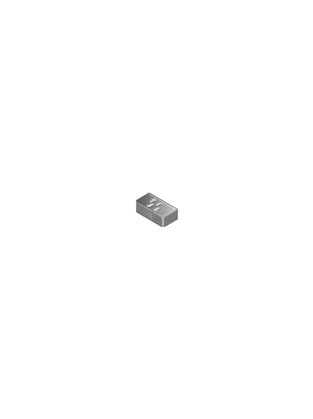
1U Hub Switch

2U Hub Switch
1U Server

2U Server

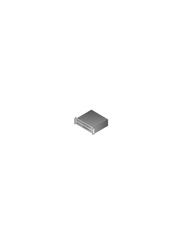
3U Server

4U Server

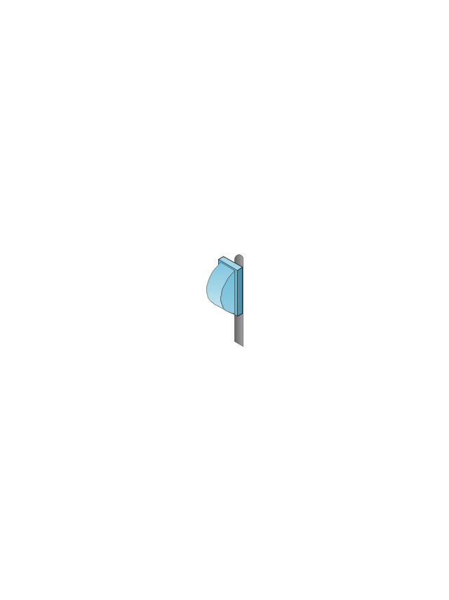
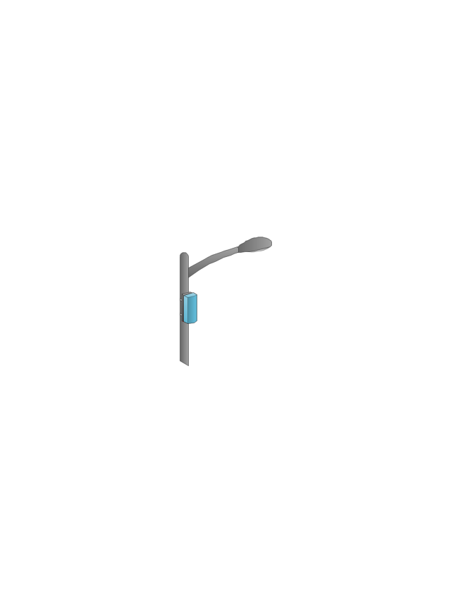
Outdoor Access Point
Indoor Access Point

Outdoor Wi-Fi Access Point

Access Point

Outdoor Mesh Node
Outdoor Mesh Node
Outdoor Access Node
Outdoor Access Node

Base Station
Cellular Phone

Outdoor Mesh Node
Active Directory Server
Smart WLAN Controller

Smart WLAN Controller

Smart Wi-Fi Access Point
Indoor Wi-Fi Access Point

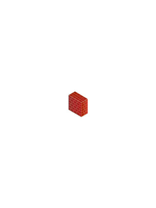
Firewall
Coverage (Yellow)
-wireless-networks---vector-stencils-library.png--diagram-flowchart-example.png)
Coverage (O-Shaped)
-wireless-networks---vector-stencils-library.png--diagram-flowchart-example.png)
Outdoor Mesh Node
Wireless network. Computer and Network Examples

Wireless Network Diagram Examples
- Telecommunication Network Diagrams | Telecommunication ...
- Drawing Symbol Of Microwaves
- Radio Connection Symbol Visio
- Symbol For Microwave
- Microwave Icon Png Symbol
- Design elements - Electron tubes | Electrical Symbols , Electrical ...
- Electrical Symbols — VHF UHF SHF | Electrical Symbols — Lamps ...
- Microwave Signal Png
- Electrical Symbols — Stations | Electrical Symbols — VHF UHF SHF ...
- Microwave Links Symbol
- Flow Chart Of Radio Transmission
- Radio Support Icon
- Example Of Terrestrial Microwave
- Electrical Symbols — Semiconductor | Electrical Symbols , Electrical ...
- Radio Transmission Flow Chart
- Electrical Symbols — Transmission Paths | Electrical Symbols ...
- Radio Communication Icon
- Electrical Drawing Software and Electrical Symbols | Electrical ...
- Design elements - Qualifying | Electrical Symbols — Qualifying ...
- Electrical Symbols — Transmission Paths | Digital Communications ...