The vector stencils library "Valves and fittings" contains 104 symbols of valve components.
Use these icons for drawing industrial piping systems; process, vacuum, and fluids piping; hydraulics piping; air and gas piping; materials distribution; and liquid transfer systems.
"A valve is a device that regulates, directs or controls the flow of a fluid (gases, liquids, fluidized solids, or slurries) by opening, closing, or partially obstructing various passageways. Valves are technically valves fittings, but are usually discussed as a separate category. In an open valve, fluid flows in a direction from higher pressure to lower pressure.
The simplest, and very ancient, valve is simply a freely hinged flap which drops to obstruct fluid (gas or liquid) flow in one direction, but is pushed open by flow in the opposite direction. This is called a check valve, as it prevents or "checks" the flow in one direction. ...
Valves are found in virtually every industrial process, including water & sewage processing, mining, power generation, processing of oil, gas & petroleum, food manufacturing, chemical & plastic manufacturing and many other fields. ...
Valves may be operated manually, either by a handle, lever, pedal or wheel. Valves may also be automatic, driven by changes in pressure, temperature, or flow. These changes may act upon a diaphragm or a piston which in turn activates the valve, examples of this type of valve found commonly are safety valves fitted to hot water systems or boilers.
More complex control systems using valves requiring automatic control based on an external input (i.e., regulating flow through a pipe to a changing set point) require an actuator. An actuator will stroke the valve depending on its input and set-up, allowing the valve to be positioned accurately, and allowing control over a variety of requirements." [Valve. Wikipedia]
The example "Design elements - Valves and fittings" was created using the ConceptDraw PRO diagramming and vector drawing software extended with the Chemical and Process Engineering solution from the Engineering area of ConceptDraw Solution Park.
Valves and fittings symbols

The vector stencils library "Valves" contains 91 symbols of valves. Use it for drawing plumbing and piping plans, schematic diagrams and blueprints of industrial piping systems; process, vacuum, and fluids piping; hydraulics piping; air and gas piping; materials distribution; and liquid transfer systems in the ConceptDraw PRO diagramming and vector drawing software extended with the Plumbing and Piping Plans solution from the Building Plans area of ConceptDraw Solution Park.
In-line valve

3-way valve

4-way valve

Screw-down valve

Lock-shield valve

Reel valve

Relief valve

Relief valve 2

Relief valve 3

Relief valve 4

Angle valve

Angle valve 2

Angle valve 3

Angle valve 4

Check valve

Check valve 2

Screwdown valve

Float operated valve

Float operated valve 2

Flanged valve

Flanged valve 2

Butterfly valve

Butterfly valve 2

Globe valve

Globe valve 2

Globe valve 3

Needle valve

Needle valve 2

Needle valve 3

Needle valve 4

Diaphragm valve

Diaphragm valve 2

Diaphragm valve 3

Wedge gate valve

Parallel side valve

Gate valve

Ball valve

Ball valve 2

Ball valve 3

Powered control valve

Powered control valve 2

Powered control valve 3

Relief angle valve, pressure

Relief angle valve, vacuum

Reducing valve

Reducing valve 2

Plug valve

Plug valve 2

Plug valve, straight through

3-way plug valve

Plug valve, T-port

Plug valve, L-port

3-way plug valve

3-way plug valve 2

3-way plug valve 3

3-way plug valve, T-port

3-way plug valve, L-port

Mixing valve

Characterized port valve

Manual isolation

Power signal

Statically loaded

Spring loaded

Spring loaded 2

Remote control

Diaphragm

Diaphragm, positioner

Chain operated

Gear operated

Solenoid

Weight loaded

Weight loaded 2

Weight loaded 3

Float operated

Float operated 2

Dash-pot

Dash-pot 2

Piston

Quick opening

Quick opening 2

Quick closing

Quick closing 2

Connecting unit

Connecting unit 2

Connecting unit 3

Motor element

Motor element, opens on failure

Motor element, closes on failure

Motor element, retains position on fail

Motor element, safe direction

Regulating

Interior Design. Piping Plan — Design Elements

Retract resistor check valve application: pneumatic cylinder, piston driven by Compressed air through 2 Retract resistor check valves.
"A check valve, clack valve, non-return valve or one-way valve is a valve that normally allows fluid (liquid or gas) to flow through it in only one direction.
Check valves are two-port valves, meaning they have two openings in the body, one for fluid to enter and the other for fluid to leave. There are various types of check valves used in a wide variety of applications. Check valves are often part of common household items. Although they are available in a wide range of sizes and costs, check valves generally are very small, simple, or inexpensive. Check valves work automatically and most are not controlled by a person or any external control; accordingly, most do not have any valve handle or stem. The bodies (external shells) of most check valves are made of plastic or metal.
An important concept in check valves is the cracking pressure which is the minimum upstream pressure at which the valve will operate. Typically the check valve is designed for and can therefore be specified for a specific cracking pressure.
Heart valves are essentially inlet and outlet check valves for the heart ventricles, since the ventricles act as pumps." [Check valve. Wikipedia]
This hydraulic schematic example was redrawn using ConceptDraw PRO diagramming and vector drawing software from the Wikimedia Commons file: Retract resistor check valve application.png.
[commons.wikimedia.org/ wiki/ File:Retract_ resistor_ check_ valve_ application.png]
The hydraulic engineering drawing example "Retract resistor check valve application" was created using the ConceptDraw PRO diagramming and vector drawing software extended with the Mechanical Engineering solution from the Engineering area of ConceptDraw Solution Park.
Hydraulic schematic

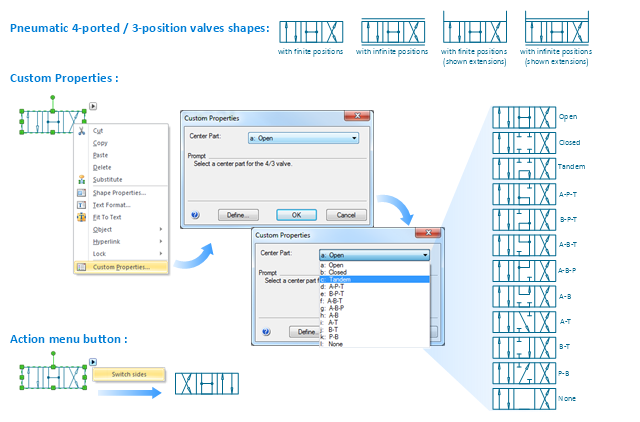
"An air-operated valve is a type of power operated valve that uses air pressure against a piston or diaphragm to produce linear or circular movement to operate a valve. Types are 2-way, 3-way and 4-way. The 2 way air-operated valves can be either normally closed or normally opened." [Air-operated valve. Wikipedia]
The Windows template "Pneumatic 4-ported 3-position valve" for the ConceptDraw PRO diagramming and vector drawing software is included in the Mechanical Engineering solution from the Engineering area of ConceptDraw Solution Park.
www.conceptdraw.com/ solution-park/ engineering-mechanical
The Windows template "Pneumatic 4-ported 3-position valve" for the ConceptDraw PRO diagramming and vector drawing software is included in the Mechanical Engineering solution from the Engineering area of ConceptDraw Solution Park.
www.conceptdraw.com/ solution-park/ engineering-mechanical
Pneumatic directional control valve
The vector stencils library "Valves" contains 91 symbols of valves. Use it for drawing plumbing and piping plans, schematic diagrams and blueprints of industrial piping systems; process, vacuum, and fluids piping; hydraulics piping; air and gas piping; materials distribution; and liquid transfer systems in the ConceptDraw PRO diagramming and vector drawing software extended with the Plumbing and Piping Plans solution from the Building Plans area of ConceptDraw Solution Park.
In-line valve
3-way valve
4-way valve
Screw-down valve
Lock-shield valve
Reel valve
Relief valve
Relief valve 2
Relief valve 3
Relief valve 4
Angle valve
Angle valve 2
Angle valve 3
Angle valve 4
Check valve
Check valve 2
Screwdown valve
Float operated valve
Float operated valve 2
Flanged valve
Flanged valve 2
Butterfly valve
Butterfly valve 2
Globe valve
Globe valve 2
Globe valve 3
Needle valve
Needle valve 2
Needle valve 3
Needle valve 4
Diaphragm valve
Diaphragm valve 2
Diaphragm valve 3
Wedge gate valve
Parallel side valve
Gate valve
Ball valve
Ball valve 2
Ball valve 3
Powered control valve
Powered control valve 2
Powered control valve 3
Relief angle valve, pressure
Relief angle valve, vacuum
Reducing valve
Reducing valve 2
Plug valve
Plug valve 2
Plug valve, straight through
3-way plug valve
Plug valve, T-port
Plug valve, L-port
3-way plug valve
3-way plug valve 2
3-way plug valve 3
3-way plug valve, T-port
3-way plug valve, L-port
Mixing valve
Characterized port valve
Manual isolation
Power signal
Statically loaded
Spring loaded
Spring loaded 2
Remote control
Diaphragm
Diaphragm, positioner
Chain operated
Gear operated
Solenoid
Weight loaded
Weight loaded 2
Weight loaded 3
Float operated
Float operated 2
Dash-pot
Dash-pot 2
Piston
Quick opening
Quick opening 2
Quick closing
Quick closing 2
Connecting unit
Connecting unit 2
Connecting unit 3
Motor element
Motor element, opens on failure
Motor element, closes on failure
Motor element, retains position on fail
Motor element, safe direction
Regulating