This technical drawing shows the machine parts assembly using joining by threaded fasteners.
"Assembling (joining of the pieces) is done by welding, binding with adhesives, riveting, threaded fasteners, or even yet more bending in the form of a crimped seam. Structural steel and sheet metal are the usual starting materials for fabrication, along with the welding wire, flux, and fasteners that will join the cut pieces. As with other manufacturing processes, both human labor and automation are commonly used. The product resulting from fabrication may be called a fabrication. Shops that specialize in this type of metal work are called fab shops. The end products of other common types of metalworking, such as machining, metal stamping, forging, and casting, may be similar in shape and function, but those processes are not classified as fabrication." [Metal fabrication. Wikipedia]
This mechanical engineering drawing example was designed using ConceptDraw PRO diagramming and vector drawing software extended with Mechanical Engineering solution from Engineering area of ConceptDraw Solution Park.

Bubble diagrams in Landscape Design with ConceptDraw DIAGRAM

Network Diagram Software Backbone Network


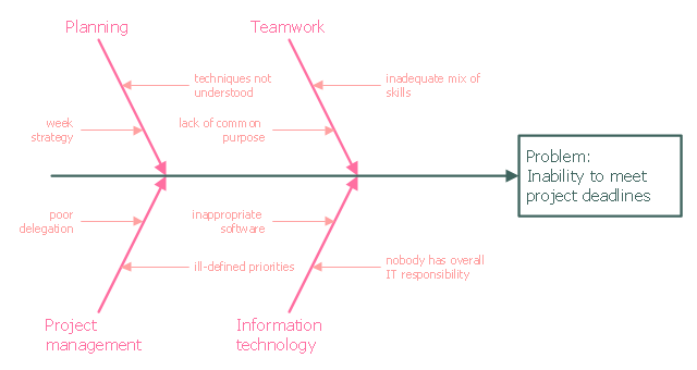
This example was created on the base of the figure from the website of the Iowa State University Center for Excellence in Learning and Teaching.
"Fishbone.
What: The fishbone technique uses a visual organizer to identify the possible causes of a problem.
Benefits: This technique discourages partial or premature solutions and demonstrates the relative importance of, and interactions between, different parts of a problem.
How: On a broad sheet of paper, draw a long arrow horizontally across the middle of the page pointing to the right. Label the arrowhead with the title of the issue to be explained. This is the "backbone" of the "fish." Draw "spurs" from this "backbone" at about 45 degrees, one for every likely cause of the problem that the group can think of; and label each. Sub-spurs can represent subsidiary causes. The group considers each spur/ sub-spur, taking the simplest first, partly for clarity but also because a simple explanation may make more complex ones unnecessary. Ideally, the fishbone is redrawn so that position along the backbone reflects the relative importance of the different parts of the problem, with the most important at the head." [celt.iastate.edu/ creativity/ techniques.html]
The fishbone diagram example "Inability to meet project deadlines" was created using the ConceptDraw PRO diagramming and vector drawing software extended with the Fishbone Diagrams solution from the Management area of ConceptDraw Solution Park.
Ishikawa diagram
- Drawing Sheet For The Mechanical Part
- Machine Drawing Sheets Drawn By Engineers
- Free Sheet Metal Drafting Drawing Symbol Pdf
- Technical drawing - Machine parts assembling | Mechanical ...
- Technical drawing - Machine parts assembling | Process Flowchart ...
- How To Draw Mechanical Machine Part
- Chemical and Process Engineering | How to Draw a Chemical ...
- Mechanical Engineering Drawing Parts
- Types Of Flow Sheet In Chemical Engineering
- Chemical Engineering Symbols For Flow Sheet Pdf
- Mechanical Sheets Symbols
- Symbol Of Design Sheet Mechanical
- Plumbing and Piping Plans | Piping and Instrumentation Diagram ...
- Mechanical Drawing Symbols | Engineering | Technical drawing ...
- Process Flowchart | Types of Flowcharts | How to Draw a Chemical ...
- Mechanical Parts Drawings
- Flow Diagram Software | How to Create a Mechanical Diagram ...
- Symbol Of Condenser In Flow Sheet
- Process Flowchart | Event-driven Process Chain Diagrams | Types ...
- Chemical Engineering Flow Sheet Examples In Block Diagram