Cisco Network Objects in ConceptDraw DIAGRAM
"Satellite Internet access is Internet access provided through communications satellites. ...
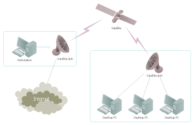
Satellite Internet generally relies on three primary components: a satellite in geostationary orbit (sometimes referred to as a geosynchronous Earth orbit, or GEO), a number of ground stations known as gateways that relay Internet data to and from the satellite via radio waves (microwave), and a VSAT (very-small-aperture terminal) dish antenna with a transceiver, located at the subscriber's premises. Other components of a satellite Internet system include a modem at the user end which links the user's network with the transceiver, and a centralized network operations center (NOC) for monitoring the entire system. Working in concert with a broadband gateway, the satellite operates a Star network topology where all network communication passes through the network's hub processor, which is at the center of the star. With this configuration, the number of remote VSATs that can be connected to the hub is virtually limitless." [Satellite Internet access. Wikipedia]
This satellite telecom network diagram example was created using the ConceptDraw PRO diagramming and vector drawing software extended with the Telecommunication Network Diagrams solution from the Computer and Networks area of ConceptDraw Solution Park.
Satellite telecom network diagram
The vector stencils library "Cisco network topology" contains 89 symbols of Cisco network devices and design elements for drawing computer network topology diagrams.
"There are two basic categories of network topologies:
(1) Physical topologies,
(2) Logical topologies.
The shape of the cabling layout used to link devices is called the physical topology of the network. This refers to the layout of cabling, the locations of nodes, and the interconnections between the nodes and the cabling. The physical topology of a network is determined by the capabilities of the network access devices and media, the level of control or fault tolerance desired, and the cost associated with cabling or telecommunications circuits.
The logical topology in contrast, is the way that the signals act on the network media, or the way that the data passes through the network from one device to the next without regard to the physical interconnection of the devices." [Network topology. Wikipedia]
The symbols example "Cisco network topology - Vector stencils library" was created using the ConceptDraw PRO diagramming and vector drawing software extended with the Cisco Network Diagrams solution from the Computer and Networks area of ConceptDraw Solution Park.
www.conceptdraw.com/ solution-park/ computer-networks-cisco
Router

Broadband router

Router firewall

Wireless router

Workgroup switch

ATM switch

ISDN switch

Multilayer switch

Protocol translator

Communications server

Transpath

Bridge

Terminal server

Route switch processor

Content engine (cache director)
-cisco-network-topology---vector-stencils-library.png--diagram-flowchart-example.png)
Management engine (ME 1100)
-cisco-network-topology---vector-stencils-library.png--diagram-flowchart-example.png)
Switch processor

ITP

Voice gateway

BBSM

ATA

SIP Proxy server

NetRanger

Cisco 1000

IP

System controller

ACE

Directory server

ADM

Cisco Unity Express

Unity server

Cisco security

CallManager

DSLAM

H.323

CDM (Content Distribution Manager)
-cisco-network-topology---vector-stencils-library.png--diagram-flowchart-example.png)
ICM

Access point

Wireless bridge

Wireless connectivity

Guard

Mobile access router

Carrier Routing System (CRS)
-cisco-network-topology---vector-stencils-library.png--diagram-flowchart-example.png)
Vault

Workstation

PC

Macintosh

Cloud, gold

Cloud, white

Cloud, standard color

Cisco security management

PBX

DPT

Government building

Headquarters, blue

Router in building

Man

Woman

Workgroup switch, subdued

Router, subdued

File server

Firewall, horizontal

Firewall, vertical

Firewall, vertical, subdued

Lock

Key

Lock and key

Car

Truck

File cabinet

Breakout box

Breakout box, blue

Host

Relational database

Modem

BBS (Bulletin Board System)
-cisco-network-topology---vector-stencils-library.png--diagram-flowchart-example.png)
Satellite

Satellite dish

UPS

RPS

MAU

PAD

PAD X.28

Diskette

Contact center

Page icon
Antenna

Antenna, blue

Radio tower

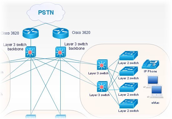
How To use Switches in Network Diagram


"At different scales diagrams may represent various levels of network granularity. At the LAN level, individual nodes may represent individual physical devices, such as hubs or file servers, while at the WAN level, individual nodes may represent entire cities. In addition, when the scope of a diagram crosses the common LAN/ MAN/ WAN boundaries, representative hypothetical devices may be depicted instead of showing all actually existing nodes. For example, if a network appliance is intended to be connected through the Internet to many end-user mobile devices, only a single such device may be depicted for the purposes of showing the general relationship between the appliance and any such device." [Computer network diagram. Wikipedia]
The physical LAN and WAN diagram template for the ConceptDraw PRO diagramming and vector drawing software is included in the Computer and Networks solution from the Computer and Networks area of ConceptDraw Solution Park.
The physical LAN and WAN diagram template for the ConceptDraw PRO diagramming and vector drawing software is included in the Computer and Networks solution from the Computer and Networks area of ConceptDraw Solution Park.
Physical LAN and WAN diagram template
Cisco Network Templates

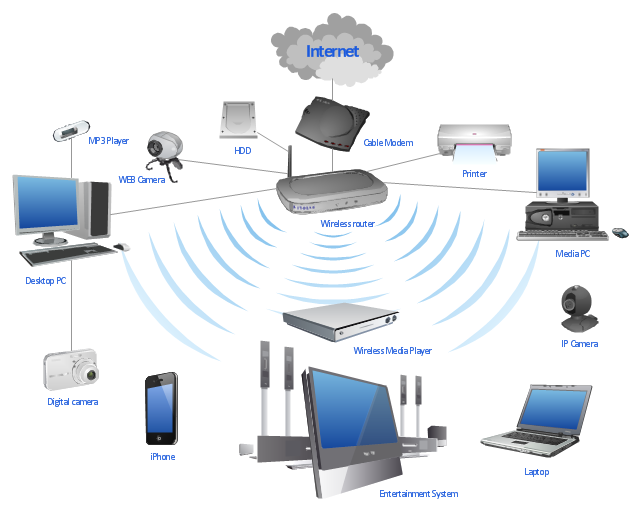
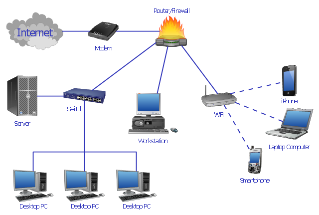
"A wireless network is any type of computer network that uses wireless data connections for connecting network nodes. Wireless networking is a method by which homes, telecommunications networks and enterprise (business) installations avoid the costly process of introducing cables into a building, or as a connection between various equipment locations. Wireless telecommunications networks are generally implemented and administered using radio communication. This implementation takes place at the physical level (layer) of the OSI model network structure. Examples of wireless networks include cell phone networks, Wi-Fi local networks and terrestrial microwave networks." [Wireless network. Wikipedia]
This wireless router network diagram example was created using the ConceptDraw PRO diagramming and vector drawing software extended with the Computer and Networks solution from the Computer and Networks area of ConceptDraw Solution Park.
This wireless router network diagram example was created using the ConceptDraw PRO diagramming and vector drawing software extended with the Computer and Networks solution from the Computer and Networks area of ConceptDraw Solution Park.
Network diagram
Used Solutions
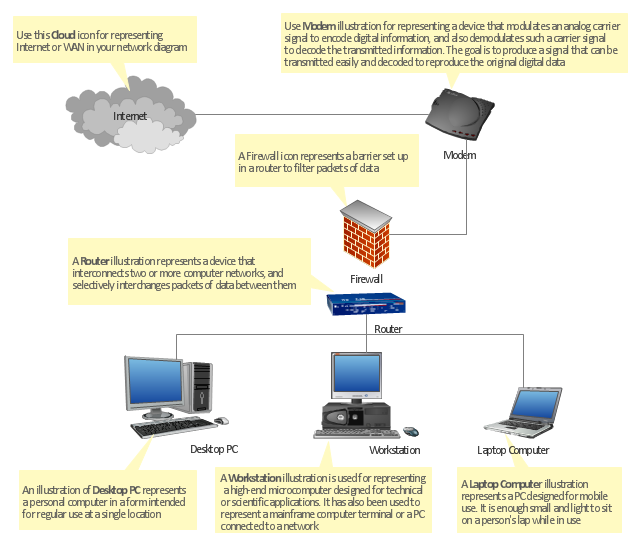
"Network planning and design is an iterative process, encompassing topological design, network-synthesis, and network-realization, and is aimed at ensuring that a new telecommunications network or service meets the needs of the subscriber and operator. Network planning process involves three main steps: 1) Topological design: This stage involves determining where to place the components and how to connect them. 2) Network-synthesis: This stage involves determining the size of the components used, subject to performance criteria such as the Grade of Service (GoS). 3) Network realization: This stage involves determining how to meet capacity requirements, and ensure reliability within the network." [Network planning and design. Wikipedia]
This computer network system design diagram example was created using the ConceptDraw PRO diagramming and vector drawing software extended with the Computer and Networks solution from the Computer and Networks area of ConceptDraw Solution Park.
This computer network system design diagram example was created using the ConceptDraw PRO diagramming and vector drawing software extended with the Computer and Networks solution from the Computer and Networks area of ConceptDraw Solution Park.
Network system design
- How To use Switches in Network Diagram | Computer network ...
- Hotel Network Topology Diagram | Star Network Topology | Wireless ...
- Wireless router network diagram | What Is a Wireless Network ...
- Satellite telecom network diagram | Internet Connectivity. Computer ...
- Wireless router network diagram | What Is a Wireless Network ...
- Physical LAN and WAN diagram - Template | Network Diagram ...
- Cloud With Modem
- Cloud Computing Diagrams | How to Connect an Image to a Topic in ...
- Computer network - Vector stencils library | In searching of ...
- Satellite telecom network diagram | Hybrid satellite and common ...
- Satellite telecom network diagram | Cloud Computing | What is ...
- Network Gateway Router | Computer network - Vector stencils library ...
- How to Install ConceptDraw on a Second Computer | Amazon Cloud ...
- The Cloud Internet Access
- Local area network (LAN). Computer and Network Examples ...
- Home area networks (HAN). Computer and Network Examples ...
- Local area network (LAN). Computer and Network Examples ...
- Www How To Connect Internet With Digram Com
- Wireless router network diagram | What Is a Wireless Network ...
- Local area network (LAN). Computer and Network Examples ...