The vector stencils library "Cisco network topology" contains 89 symbols of Cisco network devices and design elements for drawing computer network topology diagrams.
"There are two basic categories of network topologies:
(1) Physical topologies,
(2) Logical topologies.
The shape of the cabling layout used to link devices is called the physical topology of the network. This refers to the layout of cabling, the locations of nodes, and the interconnections between the nodes and the cabling. The physical topology of a network is determined by the capabilities of the network access devices and media, the level of control or fault tolerance desired, and the cost associated with cabling or telecommunications circuits.
The logical topology in contrast, is the way that the signals act on the network media, or the way that the data passes through the network from one device to the next without regard to the physical interconnection of the devices." [Network topology. Wikipedia]
The symbols example "Cisco network topology - Vector stencils library" was created using the ConceptDraw PRO diagramming and vector drawing software extended with the Cisco Network Diagrams solution from the Computer and Networks area of ConceptDraw Solution Park.
www.conceptdraw.com/ solution-park/ computer-networks-cisco
Router

Broadband router

Router firewall

Wireless router

Workgroup switch

ATM switch

ISDN switch

Multilayer switch

Protocol translator

Communications server

Transpath

Bridge

Terminal server

Route switch processor

Content engine (cache director)
-cisco-network-topology---vector-stencils-library.png--diagram-flowchart-example.png)
Management engine (ME 1100)
-cisco-network-topology---vector-stencils-library.png--diagram-flowchart-example.png)
Switch processor

ITP

Voice gateway

BBSM

ATA

SIP Proxy server

NetRanger

Cisco 1000

IP

System controller

ACE

Directory server

ADM

Cisco Unity Express

Unity server

Cisco security

CallManager

DSLAM

H.323

CDM (Content Distribution Manager)
-cisco-network-topology---vector-stencils-library.png--diagram-flowchart-example.png)
ICM

Access point

Wireless bridge

Wireless connectivity

Guard

Mobile access router

Carrier Routing System (CRS)
-cisco-network-topology---vector-stencils-library.png--diagram-flowchart-example.png)
Vault

Workstation

PC

Macintosh

Cloud, gold

Cloud, white

Cloud, standard color

Cisco security management

PBX

DPT

Government building

Headquarters, blue

Router in building

Man

Woman

Workgroup switch, subdued

Router, subdued

File server

Firewall, horizontal

Firewall, vertical

Firewall, vertical, subdued

Lock

Key

Lock and key

Car

Truck

File cabinet

Breakout box

Breakout box, blue

Host

Relational database

Modem

BBS (Bulletin Board System)
-cisco-network-topology---vector-stencils-library.png--diagram-flowchart-example.png)
Satellite

Satellite dish

UPS

RPS

MAU

PAD

PAD X.28

Diskette

Contact center

Page icon
Antenna

Antenna, blue

Radio tower

The vector stencils library "Logical symbols" contains 49 logical symbols for drawing logical network topology diagrams.
"Logical topology, or signal topology, is the arrangement of devices on a computer network and how they communicate with one another. How devices are connected to the network through the actual cables that transmit data, or the physical structure of the network, is called the physical topology. Physical topology defines how the systems are physically connected. It represents the physical layout of the devices on the network. The logical topology defines how the systems communicate across the physical topologies.
Logical topologies are bound to network protocols and describe how data is moved across the network. ... EXAMPLE : twisted pair Ethernet is a logical bus topology in a physical star topology layout. While IBM's token ring is a logical ring topology, it is physically set up in star topology." [Logical topology. Wikipedia]
The icons example "Logical symbols - Vector stencils library" was created using the ConceptDraw PRO diagramming and vector drawing software extended with the Computer and Networks solution from the Computer and Networks area of ConceptDraw Solution Park.
www.conceptdraw.com/ solution-park/ computer-and-networks
Coaxial Line Tag

Fiber Optic Line Tag

Twisted Pair Line Tag

SC2200 Signaling Controller

Bridge

Network Management Appliance

Access Server (Communications Server)
-logical-symbols---vector-stencils-library.png--diagram-flowchart-example.png)
Terminal Server

Web Browser

Security Management, Cisco

Lock and Key

Lock

Key

Relational Database

Host

CSU/DSU

WAN

University

Government building

Home Office

Telecommuter House PC

Medium Building, Regular

Headquarters, Subdued

House, Regular

Small Business

Network Connector

Dynamic Connector

Line Connector

Line-curve Connector

Bus

FDDI Ring

Peer-to-peer

Token-ring

Star

Comm-link

Curved Bus

Ethernet

Cloud

Speaker

Microphone

Router

ATM Router

ISDN Switch

ATM Switch

ATM/FastGB Etherswitch

Workgroup Switch

Small Hub

100BaseT Hub

CDDI-FDDI

The vector stencils library "Logical symbols" contains 49 logical symbols for drawing logical network topology diagrams.
"Logical topology, or signal topology, is the arrangement of devices on a computer network and how they communicate with one another. How devices are connected to the network through the actual cables that transmit data, or the physical structure of the network, is called the physical topology. Physical topology defines how the systems are physically connected. It represents the physical layout of the devices on the network. The logical topology defines how the systems communicate across the physical topologies.
Logical topologies are bound to network protocols and describe how data is moved across the network. ... EXAMPLE : twisted pair Ethernet is a logical bus topology in a physical star topology layout. While IBM's token ring is a logical ring topology, it is physically set up in star topology." [Logical topology. Wikipedia]
The icons example "Logical symbols - Vector stencils library" was created using the ConceptDraw PRO diagramming and vector drawing software extended with the Computer and Networks solution from the Computer and Networks area of ConceptDraw Solution Park.
www.conceptdraw.com/ solution-park/ computer-and-networks
"Logical topology, or signal topology, is the arrangement of devices on a computer network and how they communicate with one another. How devices are connected to the network through the actual cables that transmit data, or the physical structure of the network, is called the physical topology. Physical topology defines how the systems are physically connected. It represents the physical layout of the devices on the network. The logical topology defines how the systems communicate across the physical topologies.
Logical topologies are bound to network protocols and describe how data is moved across the network. ... EXAMPLE : twisted pair Ethernet is a logical bus topology in a physical star topology layout. While IBM's token ring is a logical ring topology, it is physically set up in star topology." [Logical topology. Wikipedia]
The icons example "Logical symbols - Vector stencils library" was created using the ConceptDraw PRO diagramming and vector drawing software extended with the Computer and Networks solution from the Computer and Networks area of ConceptDraw Solution Park.
www.conceptdraw.com/ solution-park/ computer-and-networks
Coaxial Line Tag
Fiber Optic Line Tag
Twisted Pair Line Tag
SC2200 Signaling Controller
Bridge
Network Management Appliance
Access Server (Communications Server)
Terminal Server
Web Browser
Security Management, Cisco
Lock and Key
Lock
Key
Relational Database
Host
CSU/DSU
WAN
University
Government building
Home Office
Telecommuter House PC
Medium Building, Regular
Headquarters, Subdued
House, Regular
Small Business
Network Connector
Dynamic Connector
Line Connector
Line-curve Connector
Bus
FDDI Ring
Peer-to-peer
Token-ring
Star
Comm-link
Curved Bus
Ethernet
Cloud
Speaker
Microphone
Router
ATM Router
ISDN Switch
ATM Switch
ATM/FastGB Etherswitch
Workgroup Switch
Small Hub
100BaseT Hub
CDDI-FDDI
The vector stencils library "Cisco network topology" contains 89 symbols of Cisco network devices and design elements for drawing computer network topology diagrams.
"There are two basic categories of network topologies:
(1) Physical topologies,
(2) Logical topologies.
The shape of the cabling layout used to link devices is called the physical topology of the network. This refers to the layout of cabling, the locations of nodes, and the interconnections between the nodes and the cabling. The physical topology of a network is determined by the capabilities of the network access devices and media, the level of control or fault tolerance desired, and the cost associated with cabling or telecommunications circuits.
The logical topology in contrast, is the way that the signals act on the network media, or the way that the data passes through the network from one device to the next without regard to the physical interconnection of the devices." [Network topology. Wikipedia]
The symbols example "Cisco network topology - Vector stencils library" was created using the ConceptDraw PRO diagramming and vector drawing software extended with the Cisco Network Diagrams solution from the Computer and Networks area of ConceptDraw Solution Park.
www.conceptdraw.com/ solution-park/ computer-networks-cisco
"There are two basic categories of network topologies:
(1) Physical topologies,
(2) Logical topologies.
The shape of the cabling layout used to link devices is called the physical topology of the network. This refers to the layout of cabling, the locations of nodes, and the interconnections between the nodes and the cabling. The physical topology of a network is determined by the capabilities of the network access devices and media, the level of control or fault tolerance desired, and the cost associated with cabling or telecommunications circuits.
The logical topology in contrast, is the way that the signals act on the network media, or the way that the data passes through the network from one device to the next without regard to the physical interconnection of the devices." [Network topology. Wikipedia]
The symbols example "Cisco network topology - Vector stencils library" was created using the ConceptDraw PRO diagramming and vector drawing software extended with the Cisco Network Diagrams solution from the Computer and Networks area of ConceptDraw Solution Park.
www.conceptdraw.com/ solution-park/ computer-networks-cisco
Router
Broadband router
Router firewall
Wireless router
Workgroup switch
ATM switch
ISDN switch
Multilayer switch
Protocol translator
Communications server
Transpath
Bridge
Terminal server
Route switch processor
Content engine (cache director)
Management engine (ME 1100)
Switch processor
ITP
Voice gateway
BBSM
ATA
SIP Proxy server
NetRanger
Cisco 1000
IP
System controller
ACE
Directory server
ADM
Cisco Unity Express
Unity server
Cisco security
CallManager
DSLAM
H.323
CDM (Content Distribution Manager)
ICM
Access point
Wireless bridge
Wireless connectivity
Guard
Mobile access router
Carrier Routing System (CRS)
Vault
Workstation
PC
Macintosh
Cloud, gold
Cloud, white
Cloud, standard color
Cisco security management
PBX
DPT
Government building
Headquarters, blue
Router in building
Man
Woman
Workgroup switch, subdued
Router, subdued
File server
Firewall, horizontal
Firewall, vertical
Firewall, vertical, subdued
Lock
Key
Lock and key
Car
Truck
File cabinet
Breakout box
Breakout box, blue
Host
Relational database
Modem
BBS (Bulletin Board System)
Satellite
Satellite dish
UPS
RPS
MAU
PAD
PAD X.28
Diskette
Contact center
Page icon
Antenna
Antenna, blue
Radio tower
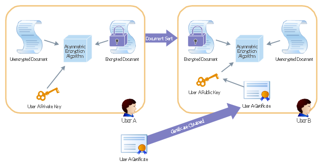
This AD diagram example was redesigned from the picture "Asymmetric
encryption" from the book "Active Directory for Dummies".
"Asymmetric Encryption:
This scenario uses a public and private key pair that is associated with each other. With this type of encryption, one of the keys is used to encrypt the data in such a way that only the corresponding second key is capable of decrypting the information. ...
In asymmetric encryption, two different keys are involved in the process: one for encrypting the document and a different but related key for decrypting the document. The two keys are generated at the same time so that if a document is encrypted with one of the keys, only the second related key can decrypt the document. ... Typically, these keys are referred to as a private key and a public key. A private key is one that is generated for a particular user and is never shared with any other user or computer. A public key is typically one of the pieces of data that’s stored in a PKI certificate. Although this type of encryption creates a very secure way of sharing data, an added benefit is you knowing that a piece of data decrypted by using a particular user’s public key must have come from that user because no other user would have the private key the document was encrypted with."
[Steve Clines and Marcia Loughry, Active Directory® For Dummies®, 2nd Edition. 2008]
The Active Directory diagram example "Asymmetric encryption" was created using the ConceptDraw PRO diagramming and vector drawing software extended with the Active Directory Diagrams solution from the Computer and Networks area of ConceptDraw Solution Park.
Active Directory diagram
Cisco Network Topology. Cisco icons, shapes, stencils and symbols

The vector stencils library "Logical symbols" contains 49 logical symbols for drawing logical network topology diagrams.
"Logical topology, or signal topology, is the arrangement of devices on a computer network and how they communicate with one another. How devices are connected to the network through the actual cables that transmit data, or the physical structure of the network, is called the physical topology. Physical topology defines how the systems are physically connected. It represents the physical layout of the devices on the network. The logical topology defines how the systems communicate across the physical topologies.
Logical topologies are bound to network protocols and describe how data is moved across the network. ... EXAMPLE : twisted pair Ethernet is a logical bus topology in a physical star topology layout. While IBM's token ring is a logical ring topology, it is physically set up in star topology." [Logical topology. Wikipedia]
The icons example "Logical symbols - Vector stencils library" was created using the ConceptDraw PRO diagramming and vector drawing software extended with the Computer and Networks solution from the Computer and Networks area of ConceptDraw Solution Park.
www.conceptdraw.com/ solution-park/ computer-and-networks
"Logical topology, or signal topology, is the arrangement of devices on a computer network and how they communicate with one another. How devices are connected to the network through the actual cables that transmit data, or the physical structure of the network, is called the physical topology. Physical topology defines how the systems are physically connected. It represents the physical layout of the devices on the network. The logical topology defines how the systems communicate across the physical topologies.
Logical topologies are bound to network protocols and describe how data is moved across the network. ... EXAMPLE : twisted pair Ethernet is a logical bus topology in a physical star topology layout. While IBM's token ring is a logical ring topology, it is physically set up in star topology." [Logical topology. Wikipedia]
The icons example "Logical symbols - Vector stencils library" was created using the ConceptDraw PRO diagramming and vector drawing software extended with the Computer and Networks solution from the Computer and Networks area of ConceptDraw Solution Park.
www.conceptdraw.com/ solution-park/ computer-and-networks
Coaxial Line Tag
Fiber Optic Line Tag
Twisted Pair Line Tag
SC2200 Signaling Controller
Bridge
Network Management Appliance
Access Server (Communications Server)
Terminal Server
Web Browser
Security Management, Cisco
Lock and Key
Lock
Key
Relational Database
Host
CSU/DSU
WAN
University
Government building
Home Office
Telecommuter House PC
Medium Building, Regular
Headquarters, Subdued
House, Regular
Small Business
Network Connector
Dynamic Connector
Line Connector
Line-curve Connector
Bus
FDDI Ring
Peer-to-peer
Token-ring
Star
Comm-link
Curved Bus
Ethernet
Cloud
Speaker
Microphone
Router
ATM Router
ISDN Switch
ATM Switch
ATM/FastGB Etherswitch
Workgroup Switch
Small Hub
100BaseT Hub
CDDI-FDDI
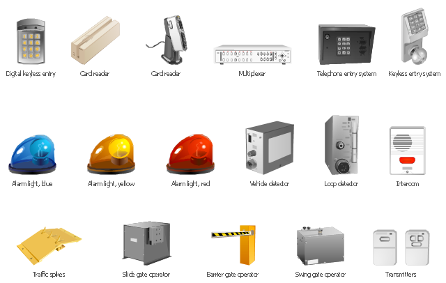
The vector clipart library Access and security contains 17 images of access control and security system equipment.
"In the fields of physical security and information security, access control is the selective restriction of access to a place or other resource. The act of accessing may mean consuming, entering, or using. Permission to access a resource is called authorization.
Locks and login credentials are two analogous mechanisms of access control. ...
The term access control refers to the practice of restricting entrance to a property, a building, or a room to authorized persons. Physical access control can be achieved by a human (a guard, bouncer, or receptionist), through mechanical means such as locks and keys, or through technological means such as access control systems like the mantrap. Within these environments, physical key management may also be employed as a means of further managing and monitoring access to mechanically keyed areas or access to certain small assets." [Access control. Wikipedia]
Use the vector stencils library Access and security to draw illustrations and diagrams of safety and security system equipment using the ConceptDraw PRO diagramming and vector drawing software.
The clipart example "Design elements - Access and security" is included in the Safety and Security solution from the Illustration area of ConceptDraw Solution Park.
Vector clip art
- Lock and key - Conceptdraw.com
- Lock and Key - Conceptdraw.com
- Lock
- How to Protect a Document From Performing Unwanted Operations ...
- Design elements - Alarm and access control | Design elements ...
- Cisco Network Templates | Cisco Network Diagrams | Network ...
- Cisco Network Topology. Cisco icons, shapes, stencils and symbols ...
- Cisco WAN
- Security system plan
- Wireless broadband network diagram
- Switches - Vector stencils library | Switches and relays - Vector ...
- Wireless broadband network diagram - Conceptdraw.com
- How To use Switches in Network Diagram | Cisco Network Objects ...
- Cabinet Design Software | Design elements - Cabinets and ...
- Cabinet Design Software | Interior Design Machines and Equipment ...
- Logical symbols - Vector stencils library
- Crow's foot ERD - Educational data base
- Cisco WAN - Vector stencils library | Cisco WAN. Cisco icons ...
- Network Topologies
- Network Gateway Router | Wireless router network diagram ...