"The Ethernet physical layer is the physical layer component of the Ethernet family of computer network standards.
The Ethernet physical layer evolved over a considerable time span and encompasses quite a few physical media interfaces and several magnitudes of speed. The speed ranges from 1 Mbit/ s to 100 Gbit/ s, while the physical medium can range from bulky coaxial cable to twisted pair and optical fiber. In general, network protocol stack software will work similarly on all physical layers.
10-gigabit Ethernet was already used in both enterprise and carrier networks by 2007, with 40 Gbit/ s and 100 Gbit/ s Ethernet ratified. ...
Many Ethernet adapters and switch ports support multiple speeds, using autonegotiation to set the speed and duplex for the best values supported by both connected devices. If auto-negotiation fails, a multiple-speed device will sense the speed used by its partner, but will assume half-duplex. A 10/ 100 Ethernet port supports 10BASE-T and 100BASE-TX. A 10/ 100/ 1000 Ethernet port supports 10BASE-T, 100BASE-TX, and 1000BASE-T." [Ethernet physical layer. Wikipedia]
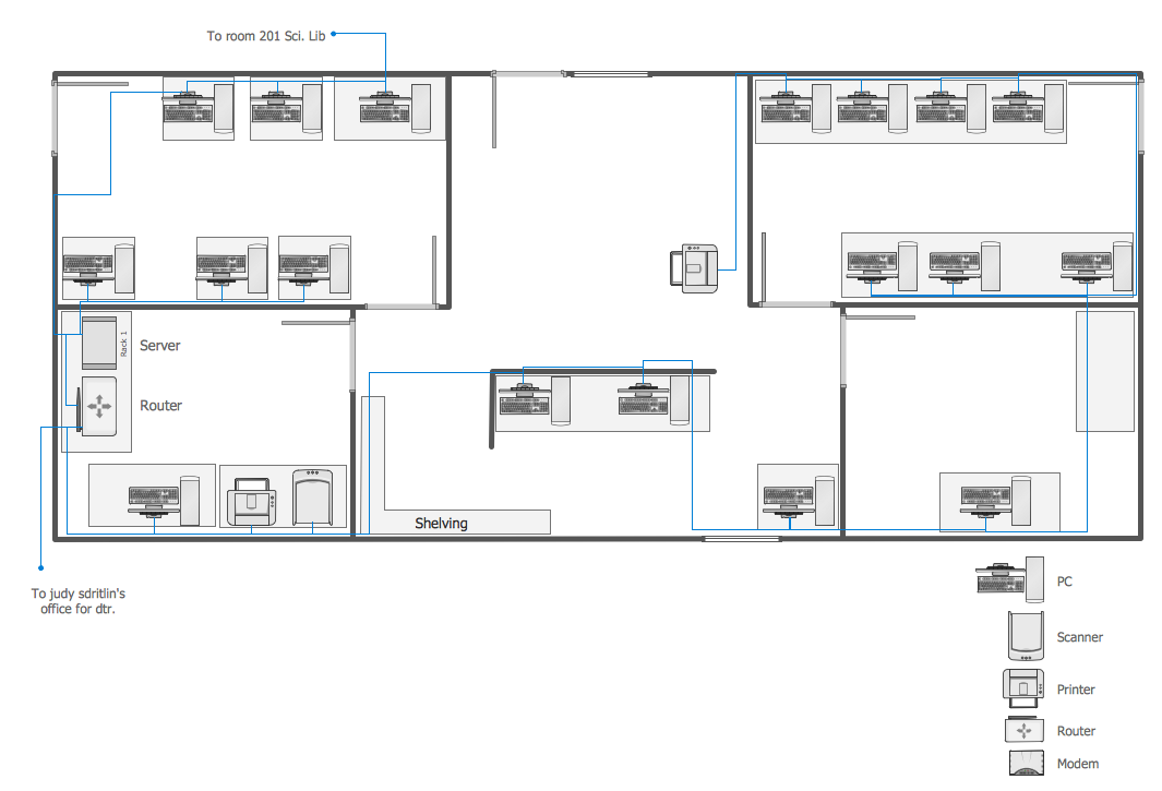
The LAN equipment and cabling layout floorplan example "Ethernet local area network layout floor plan" was created using the ConceptDraw PRO diagramming and vector drawing software extended with the Network Layout Floor Plans solution from the Computer and Networks area of ConceptDraw Solution Park.
The Ethernet physical layer evolved over a considerable time span and encompasses quite a few physical media interfaces and several magnitudes of speed. The speed ranges from 1 Mbit/ s to 100 Gbit/ s, while the physical medium can range from bulky coaxial cable to twisted pair and optical fiber. In general, network protocol stack software will work similarly on all physical layers.
10-gigabit Ethernet was already used in both enterprise and carrier networks by 2007, with 40 Gbit/ s and 100 Gbit/ s Ethernet ratified. ...
Many Ethernet adapters and switch ports support multiple speeds, using autonegotiation to set the speed and duplex for the best values supported by both connected devices. If auto-negotiation fails, a multiple-speed device will sense the speed used by its partner, but will assume half-duplex. A 10/ 100 Ethernet port supports 10BASE-T and 100BASE-TX. A 10/ 100/ 1000 Ethernet port supports 10BASE-T, 100BASE-TX, and 1000BASE-T." [Ethernet physical layer. Wikipedia]
The LAN equipment and cabling layout floorplan example "Ethernet local area network layout floor plan" was created using the ConceptDraw PRO diagramming and vector drawing software extended with the Network Layout Floor Plans solution from the Computer and Networks area of ConceptDraw Solution Park.
Ethernet LAN layout floorplan

 Network Layout Floor Plans
Network Layout Floor Plans solution extends ConceptDraw DIAGRAM software functionality with powerful tools for quick and efficient documentation the network equipment and displaying its location on the professionally designed Network Layout Floor Plans. Never before creation of Network Layout Floor Plans, Network Communication Plans, Network Topologies Plans and Network Topology Maps was not so easy, convenient and fast as with predesigned templates, samples, examples and comprehensive set of vector design elements included to the Network Layout Floor Plans solution. All listed types of plans will be a good support for the future correct cabling and installation of network equipment.
This network layout floorplan example was drawn on the base of the picture "Ethernet cable layout" illustrating "UGA Technical Network Liaison Handbook" from the website of the University of Georgia.
[netinfo.uga.edu/ tnlhand/ landiag.gif]
"The Ethernet physical layer is the physical layer component of the Ethernet family of computer network standards.
The Ethernet physical layer evolved over a considerable time span and encompasses quite a few physical media interfaces and several magnitudes of speed. The speed ranges from 1 Mbit/ s to 100 Gbit/ s, while the physical medium can range from bulky coaxial cable to twisted pair and optical fiber. In general, network protocol stack software will work similarly on all physical layers.
10-gigabit Ethernet was already used in both enterprise and carrier networks by 2007, with 40 Gbit/ s and 100 Gbit/ s Ethernet ratified." [Ethernet physical layer. Wikipedia]
The network layout floorplan example "Ethernet cable layout" was created using the ConceptDraw PRO diagramming and vector drawing software extended with the Network Layout Floor Plans solution from the Computer and Networks area of ConceptDraw Solution Park.
Network layout floorplan

"The Ethernet physical layer is the physical layer component of the Ethernet family of computer network standards.
The Ethernet physical layer evolved over a considerable time span and encompasses quite a few physical media interfaces and several magnitudes of speed. The speed ranges from 1 Mbit/ s to 100 Gbit/ s, while the physical medium can range from bulky coaxial cable to twisted pair and optical fiber. In general, network protocol stack software will work similarly on all physical layers.
10-gigabit Ethernet was already used in both enterprise and carrier networks by 2007, with 40 Gbit/ s and 100 Gbit/ s Ethernet ratified. ...
Many Ethernet adapters and switch ports support multiple speeds, using autonegotiation to set the speed and duplex for the best values supported by both connected devices. If auto-negotiation fails, a multiple-speed device will sense the speed used by its partner, but will assume half-duplex. A 10/ 100 Ethernet port supports 10BASE-T and 100BASE-TX. A 10/ 100/ 1000 Ethernet port supports 10BASE-T, 100BASE-TX, and 1000BASE-T." [Ethernet physical layer. Wikipedia]
The LAN equipment and cabling layout floorplan example "Ethernet local area network layout floor plan" was created using the ConceptDraw PRO diagramming and vector drawing software extended with the Network Layout Floor Plans solution from the Computer and Networks area of ConceptDraw Solution Park.
Ethernet LAN layout floorplan
"In computer networks, networked computing devices pass data to each other along data connections. The connections (network links) between nodes are established using either cable media or wireless media. ...
Network computer devices that originate, route and terminate the data are called network nodes. Nodes can include hosts such as personal computers, phones, servers as well as networking hardware. ...
Network links.
The communication media used to link devices to form a computer network include electrical cable (HomePNA, power line communication, G.hn), optical fiber (fiber-optic communication), and radio waves (wireless networking). In the OSI model, these are defined at layers 1 and 2 - the physical layer and the data link layer.
A widely adopted family of communication media used in local area network (LAN) technology is collectively known as Ethernet. The media and protocol standards that enable communication between networked devices over Ethernet are defined by IEEE 802.3. Ethernet transmit data over both copper and fiber cables. Wireless LAN standards (e.g. those defined by IEEE 802.11) use radio waves, or others use infrared signals as a transmission medium. Power line communication uses a building's power cabling to transmit data. ...
Network nodes.
Apart from the physical communications media described above, networks comprise additional basic system building blocks, such as network interface controller (NICs), repeaters, hubs, bridges, switches, routers, modems, and firewalls." [Computer network. Wikipedia]
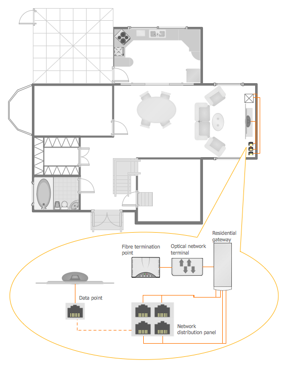
The network equipment and cabling layout floorplan template for the ConceptDraw PRO diagramming and vector drawing software is included in the Network Layout Floor Plans solution from the Computer and Networks area of ConceptDraw Solution Park.
Network computer devices that originate, route and terminate the data are called network nodes. Nodes can include hosts such as personal computers, phones, servers as well as networking hardware. ...
Network links.
The communication media used to link devices to form a computer network include electrical cable (HomePNA, power line communication, G.hn), optical fiber (fiber-optic communication), and radio waves (wireless networking). In the OSI model, these are defined at layers 1 and 2 - the physical layer and the data link layer.
A widely adopted family of communication media used in local area network (LAN) technology is collectively known as Ethernet. The media and protocol standards that enable communication between networked devices over Ethernet are defined by IEEE 802.3. Ethernet transmit data over both copper and fiber cables. Wireless LAN standards (e.g. those defined by IEEE 802.11) use radio waves, or others use infrared signals as a transmission medium. Power line communication uses a building's power cabling to transmit data. ...
Network nodes.
Apart from the physical communications media described above, networks comprise additional basic system building blocks, such as network interface controller (NICs), repeaters, hubs, bridges, switches, routers, modems, and firewalls." [Computer network. Wikipedia]
The network equipment and cabling layout floorplan template for the ConceptDraw PRO diagramming and vector drawing software is included in the Network Layout Floor Plans solution from the Computer and Networks area of ConceptDraw Solution Park.
LAN equipment and cabling layout floorplan template

The vector stencils library "Network layout floorplan" contain 34 symbol icons for drawing computer network floor plans and communication equipment and cabling layouts.
"Networking hardware may also be known as network equipment or computer networking devices. Units which are the last receiver or generate data are called hosts or data terminal equipment.
All these terms refer to devices facilitating the use of a computer network. Specifically, they mediate data in a computer network. ...
Typically, networking hardware includes gateways, routers, network bridges, switches, hubs, and repeaters. But it also includes hybrid network devices such as multilayer switches, protocol converters, bridge routers, proxy servers, firewalls, network address translators, multiplexers, network interface controllers, wireless network interface controllers, modems, ISDN terminal adapters, line drivers, wireless access points, networking cables and other related hardware.
The most common kind of networking hardware today is a copper-based Ethernet adapter because of its standard inclusion on most modern computer systems. Wireless networking has, however, become increasingly popular, especially for portable and handheld devices.
Other hardware prevalent in computer networking includes data center equipment (such as file servers, database servers and storage areas), network services (such as DNS, DHCP, email, etc.) as well as devices which assure content delivery." [Networking hardware. Wikipedia]
The shapes example "Design elements - Network layout floorplan" was created using the ConceptDraw PRO diagramming and vector drawing software extended with the Network Layout Floor Plans solution from the Computer and Networks area of ConceptDraw Solution Park.
Network layout floor plan symbols

Home Networking
Network Mapper
Network Gateway Router


The vector stencils library "Logical symbols" contains 49 logical symbols for drawing logical network topology diagrams.
"Logical topology, or signal topology, is the arrangement of devices on a computer network and how they communicate with one another. How devices are connected to the network through the actual cables that transmit data, or the physical structure of the network, is called the physical topology. Physical topology defines how the systems are physically connected. It represents the physical layout of the devices on the network. The logical topology defines how the systems communicate across the physical topologies.
Logical topologies are bound to network protocols and describe how data is moved across the network. ... EXAMPLE : twisted pair Ethernet is a logical bus topology in a physical star topology layout. While IBM's token ring is a logical ring topology, it is physically set up in star topology." [Logical topology. Wikipedia]
The icons example "Logical symbols - Vector stencils library" was created using the ConceptDraw PRO diagramming and vector drawing software extended with the Computer and Networks solution from the Computer and Networks area of ConceptDraw Solution Park.
www.conceptdraw.com/ solution-park/ computer-and-networks
Coaxial Line Tag

Fiber Optic Line Tag

Twisted Pair Line Tag

SC2200 Signaling Controller

Bridge

Network Management Appliance

Access Server (Communications Server)
-logical-symbols---vector-stencils-library.png--diagram-flowchart-example.png)
Terminal Server

Web Browser

Security Management, Cisco

Lock and Key

Lock

Key

Relational Database

Host

CSU/DSU

WAN

University

Government building

Home Office

Telecommuter House PC

Medium Building, Regular

Headquarters, Subdued

House, Regular

Small Business

Network Connector

Dynamic Connector

Line Connector

Line-curve Connector

Bus

FDDI Ring

Peer-to-peer

Token-ring

Star

Comm-link

Curved Bus

Ethernet

Cloud

Speaker

Microphone

Router

ATM Router

ISDN Switch

ATM Switch

ATM/FastGB Etherswitch

Workgroup Switch

Small Hub

100BaseT Hub

CDDI-FDDI

"Logical topology, or signal topology, is the arrangement of devices on a computer network and how they communicate with one another. How devices are connected to the network through the actual cables that transmit data, or the physical structure of the network, is called the physical topology. Physical topology defines how the systems are physically connected. It represents the physical layout of the devices on the network. The logical topology defines how the systems communicate across the physical topologies.
Logical topologies are bound to network protocols and describe how data is moved across the network. ...
EXAMPLE : twisted pair Ethernet is a logical bus topology in a physical star topology layout. while IBM's token ring is a logical ring topology, it is physically set up in star topology." [Logical topology. Wikipedia]
This Cisco logical computer network diagram example was created using the ConceptDraw PRO diagramming and vector drawing software extended with the Cisco Network Diagrams solution from the Computer and Networks area of ConceptDraw Solution Park.
Logical network topology diagram

Network Printer

Network Diagram Software. LAN Network Diagrams. Physical Office Network Diagrams

Network Glossary Definition

- Network Layout Floor Plans | Network Layout | Design elements ...
- Network Layout Floor Plans | Ethernet local area network layout floor ...
- Ethernet local area network layout floor plan | Network Layout Floor ...
- Network Layout Floor Plans | Ethernet local area network layout floor ...
- Ethernet local area network layout floor plan | Ethernet local area ...
- Network Layout | Network Layout Floor Plans | Network ...
- Design elements - Network layout floorplan | Ethernet local area ...
- ConceptDraw PRO Network Diagram Tool | Design elements ...
- Network Layout Floor Plans | Network Layout | Wireless Networks ...
- Network Layout Floor Plans | Network Layout | Ethernet local area ...
- Ethernet local area network layout floor plan | Network layout ...
- Ethernet local area network layout floor plan | Gym and Spa Area ...
- Ethernet local area network layout floor plan
- Network Layout Floor Plans | Cafe and Restaurant Floor Plan ...
- Ethernet local area network layout floor plan | Network Diagram ...
- Ethernet local area network layout floor plan | Local network ...
- Ethernet Network Diagram Floor Layout Visio Stencil
- Ethernet local area network layout floor plan | Outlets - Vector ...
- Network Topologies | ConceptDraw PRO Network Diagram Tool ...
- Network Layout | Ethernet local area network layout floor plan ...