Entity Relationship Diagram Symbols

ERD Symbols and Meanings


"Crow's Foot notation is used in Barker's Notation, SSADM and Information Engineering. Crow's Foot diagrams represent entities as boxes, and relationships as lines between the boxes. Different shapes at the ends of these lines represent the cardinality of the relationship." [Entity–relationship model. Wikipedia]
The vector stencils library ERD, crow's foot notation contains 18 symbols for creating the ER-diagrams using the ConceptDraw PRO diagramming nd vector drawing software.
The example"Design elements - ERD solution (crow's foot notation)" is included in the Entity-Relationship Diagram (ERD) solution from the Software Development area of ConceptDraw Solution Park.
Crow's foot ERD
.png--diagram-flowchart-example.png)
 Crow's Foot Notation
Crow’s Foot Notation solution extends ConceptDraw DIAGRAM software with powerful drawing tools, samples and library of predesigned vector Crow's Foot notation icons to help you easy describe the databases using the Entity-Relationship models and design professional-looking ER diagrams based on the popular Crow's Foot notation.
ER Diagram Styles

"In software engineering, an entity–relationship model (ER model) is a data model for describing a database in an abstract way. ...
Crow's Foot notation is used in Barker's Notation, SSADM and Information Engineering. Crow's Foot diagrams represent entities as boxes, and relationships as lines between the boxes. Different shapes at the ends of these lines represent the cardinality of the relationship." [Entity–relationship model. Wikipedia]
This ERD example was redesigned using the ConceptDraw PRO diagramming and vector drawing software from the educational data base model. [www2.cs.uregina.ca/ ~bernatja/ crowsfoot.html]
The example "Entity-relationship diagram (Crow's foot notation)" is included in the Entity-Relationship Diagram (ERD) solution from the Software Development area of ConceptDraw Solution Park.
Crow's foot ERD
.png--diagram-flowchart-example.png)
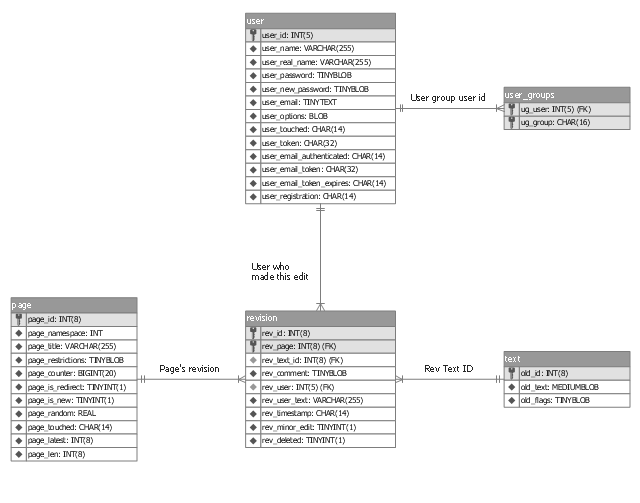
This ER-diagram sample shows a data model of wiki system (a part of MediaWiki database schema) in Information Engineering notation. It was designed on the base of the Wikimedia Commons file: Data model in IE.png. [commons.wikimedia.org/ wiki/ File:Data_ model_ in_ IE.png]
This file is licensed under the Creative Commons Attribution-Share Alike 3.0 Unported license. [creativecommons.org/ licenses/ by-sa/ 3.0/ deed.en]
The crow's foot notation ER-diagram example "Data model in IE" was created using the ConceptDraw PRO diagramming and vector drawing software extended with the Crow’s Foot Notation solution from the Software Development area of ConceptDraw Solution Park.
ERD
Data Flow Diagram Symbols. DFD Library

Entity Relationship Diagram Software Engineering

 Entity-Relationship Diagram (ERD)
An Entity-Relationship Diagram (ERD) is a visual presentation of entities and relationships. That type of diagrams is often used in the semi-structured or unstructured data in databases and information systems. At first glance ERD is similar to a flowch
- Design elements - ERD (crow's foot notation ) | Entity Relationship ...
- Er Notation
- Information Engineering Diagram
- Design elements - ERD (crow's foot notation ) | Martin Notation
- Chen Notation | Design elements - ER diagram (Chen notation ...
- Information Engineering Style Erds
- Design elements - ERD (crow's foot notation ) | Entity-Relationship ...
- Entity Relationship Diagram Symbols | Components of ER Diagram ...
- Martin ERD Diagram | Chen ERD Diagram | Entity Relationship ...