Mechanical Drawing Symbols

 HVAC Plans
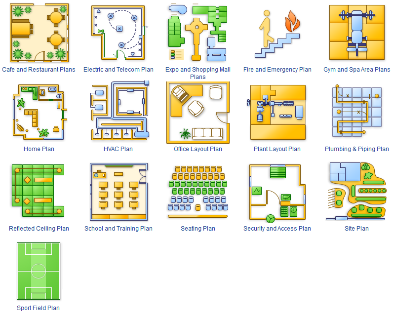
Use HVAC Plans solution to create professional, clear and vivid HVAC-systems design plans, which represent effectively your HVAC marketing plan ideas, develop plans for modern ventilation units, central air heaters, to display the refrigeration systems for automated buildings control, environmental control, and energy systems.
HVAC Marketing Plan
Interior Design. Registers, Drills and Diffusers — Design Elements

ConceptDraw Arrows10 Technology
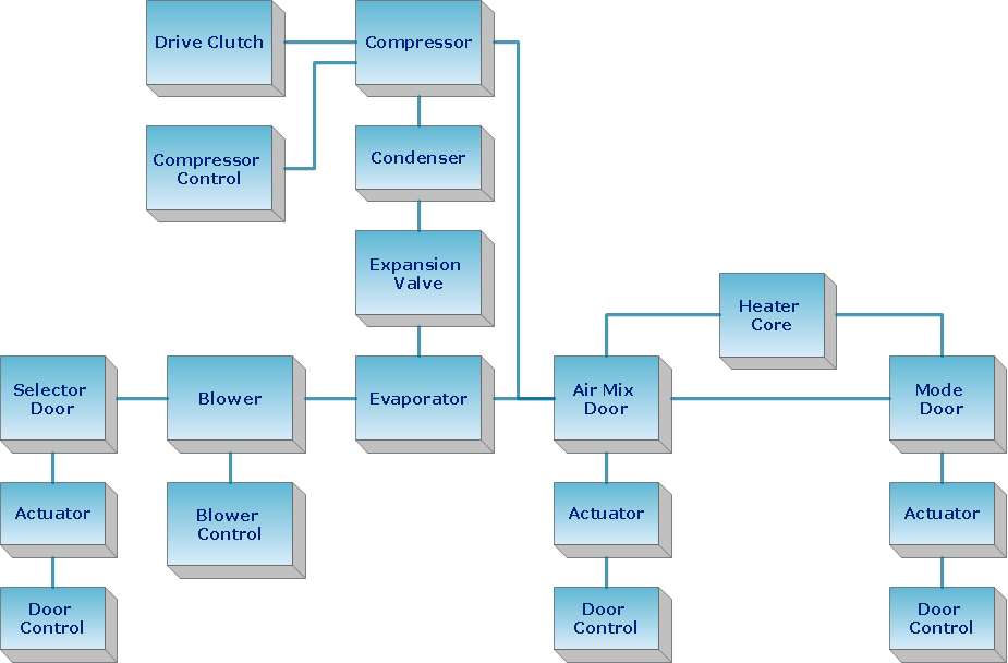
 Block Diagrams
Block diagrams solution extends ConceptDraw DIAGRAM software with templates, samples and libraries of vector stencils for drawing the block diagrams.
Blueprint Software
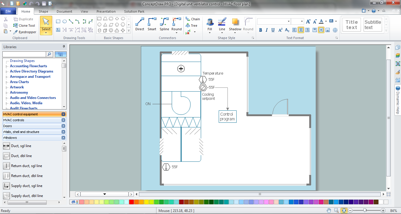
This HVAC floor plan sample shows the ventilation duct system layout.
"Ducts are used in heating, ventilation, and air conditioning (HVAC) to deliver and remove air. The needed airflows include, for example, supply air, return air, and exhaust air. Ducts commonly also deliver ventilation air as part of the supply air. As such, air ducts are one method of ensuring acceptable indoor air quality as well as thermal comfort.
A duct system is also called ductwork. Planning (laying out), sizing, optimizing, detailing, and finding the pressure losses through a duct system is called duct design." [Duct (flow). Wikipedia]
The HVAC floor plan example "Ductwork layout" was created using the ConceptDraw DIAGRAM diagramming and vector drawing software extended with the HVAC Plans solution from the Building Plans area of ConceptDraw Solution Park.
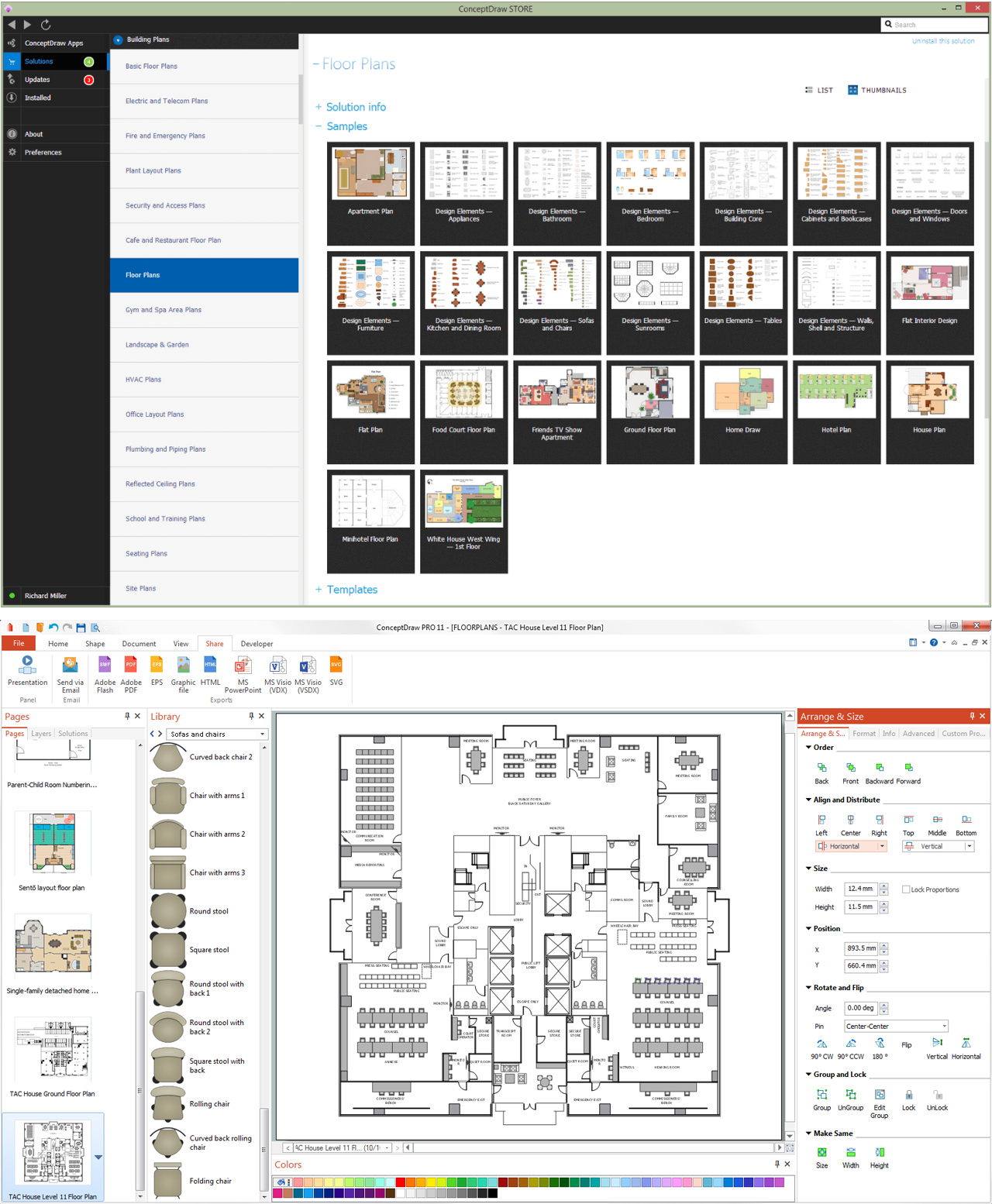
HVAC floor plan

How To use Building Plan Examples

- HVAC Plans | Plumbing and Piping Plans | Sanitary Working ...
- HVAC Plans | Android User Interface | Venn Diagrams | Ac Plant ...
- RCP - HVAC layout | Cafe electrical floor plan | Lecture theatre ...
- Working Drawing Of Some Mechanical Components
- How to Create a HVAC Plan | Design elements - HVAC ductwork ...
- Reflected Ceiling Plans | Continent Maps | Working Drawing Of ...
- Hvac Working Principle With Block Diagra
- Ducting Drawings Pdf
- Hvac Working Principle With Diagram Pdf
- Plumbing and Piping Plans | HVAC Plans | Sanitery Drawing On The ...