 HVAC Plans
Use HVAC Plans solution to create professional, clear and vivid HVAC-systems design plans, which represent effectively your HVAC marketing plan ideas, develop plans for modern ventilation units, central air heaters, to display the refrigeration systems for automated buildings control, environmental control, and energy systems.
HVAC Marketing Plan
HVAC Business Plan
This reflected ceiling plan sample was created on the base of the article "How to Read a Reflected Ceiling Plan" from wikiHow.com.
"A reflected ceiling plan (RCP) is a drawing, which shows the items that are located on the ceiling of a room or space. It is referred to as a reflected ceiling plan since it is drawn to display a view of the ceiling as if it was reflected onto a mirror on the floor. This way the reflected ceiling plan has the same orientation as the floor plan associated with it. It is as if the ceiling was see-through and you could see right through it to the floor below. Architects and interior designers draw reflected ceiling plans when designing spaces." [wikihow.com/ Read-a-Reflected-Ceiling-Plan]
The HVAC layout example "RCP- HVAC layout" was created using the ConceptDraw DIAGRAM diagramming and vector drawing software extended with the Reflected Ceiling Plans solution from the Building Plans area of ConceptDraw Solution Park.
Reflected ceiling plan

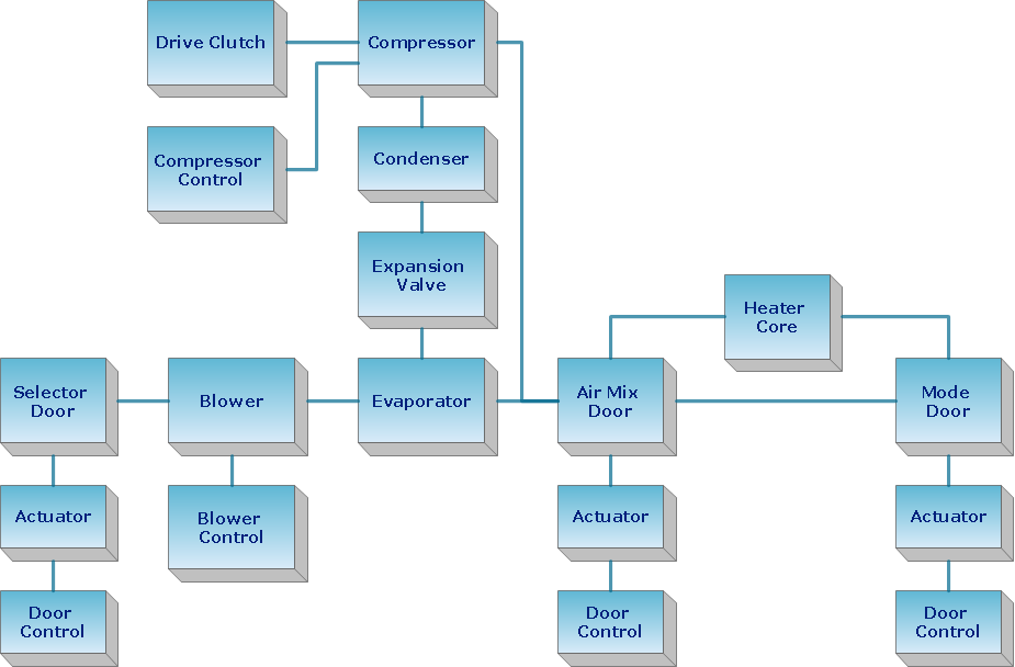
Create Block Diagram
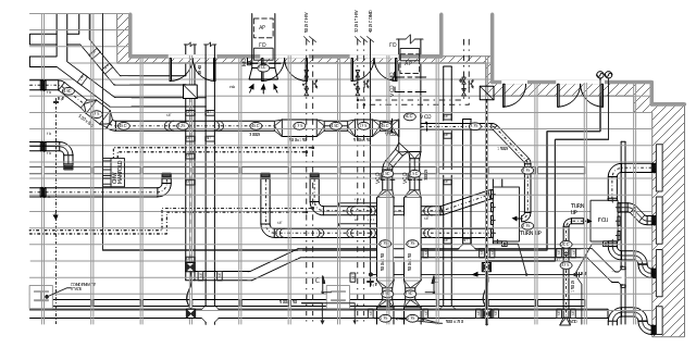
This mechanical systems drawing sample was designed on the base of Wikimedia Commons file: Building services coordinated drawing.JPG.
[commons.wikimedia.org/ wiki/ File:Building_ services_ coordinated_ drawing.JPG ]
This file is licensed under the Creative Commons Attribution-Share Alike 3.0 Unported license. [creativecommons.org/ licenses/ by-sa/ 3.0/ deed.en]
"Mechanical systems drawing is a type of technical drawing that shows information about heating, ventilating, air conditioning and transportation around the building (Elevators or Lifts and Escalator). It is a powerful tool that helps analyze complex systems. These drawings are often a set of detailed drawings used for construction projects; it is a requirement for all HVAC work. They are based on the floor and reflected ceiling plans of the architect. After the mechanical drawings are complete, they become part of the construction drawings, which is then used to apply for a building permit. They are also used to determine the price of the project." [Mechanical systems drawing. Wikipedia]
The mechanical systems drawing example "Building services coordinated drawing" was designed using ConceptDraw DIAGRAM software extended with HVAC Plans solution from the Building Plans area of ConceptDraw Solution Park.
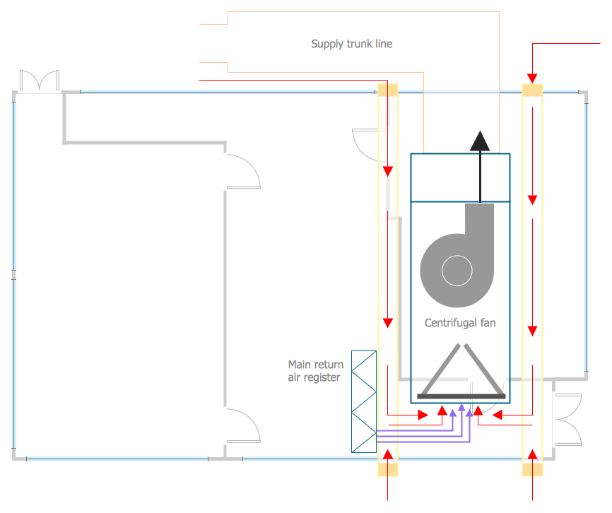
This HVAC plan sample shows the air handler layout on the floor plan.
"An air handler, or air handling unit (often abbreviated to AHU), is a device used to condition and circulate air as part of a heating, ventilating, and air-conditioning (HVAC) system. An air handler is usually a large metal box containing a blower, heating or cooling elements, filter racks or chambers, sound attenuators, and dampers. Air handlers usually connect to a ductwork ventilation system that distributes the conditioned air through the building and returns it to the AHU. Sometimes AHUs discharge (supply) and admit (return) air directly to and from the space served without ductwork.
Small air handlers, for local use, are called terminal units, and may only include an air filter, coil, and blower; these simple terminal units are called blower coils or fan coil units. A larger air handler that conditions 100% outside air, and no recirculated air, is known as a makeup air unit (MAU). An air handler designed for outdoor use, typically on roofs, is known as a packaged unit (PU) or rooftop unit (RTU)." [Air handler. Wikipedia]
The floor plan example "Air handler - HVAC plan" was created using the ConceptDraw DIAGRAM diagramming and vector drawing software extended with the HVAC Plans solution from the Building Plans area of ConceptDraw Solution Park.
Floor plan

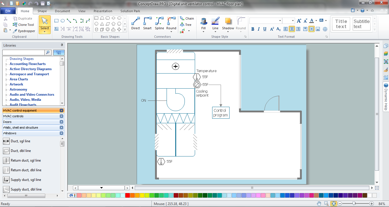
The vector stencils library "HVAC controls" contains 23 symbols of HVAC controls (sensors, actuators, timers, controllers, I/ O points). Use it for drawing HVAC system diagrams, controls drawings, and automated building control and environmental control systems design. The example "HVAC controls - Vector stencils library" was created using the ConceptDraw PRO diagramming and vector drawing software extended with the HVAC Plans solution from the Building Plans area of ConceptDraw Solution Park.
Temperature sensor

Humidity sensor

Enthalpy sensor

Pressure sensor

Flow sensor

Velocity sensor

Voltage sensor

General purpose sensor

Light sensor

Rotation sensor

Vibration sensor

Timer

Current sensor

Power sensor

Air quality sensor

Level

End switch

Smoke detector

Power connection

Actuator

I/O point

Label

Wire note

The vector stencil library "HVAC ductwork" contains 63 duct and vent symbols.
Use it for drawing HVAC system diagrams, heating, ventilation, air conditioning, refrigeration, automated building control, and environmental control design floor
plans and equipment layouts.
"Ducts are used in heating, ventilation, and air conditioning (HVAC) to deliver and remove air. These needed airflows include, for example, supply air, return air, and exhaust air. Ducts also deliver, most commonly as part of the supply air, ventilation air. As such, air ducts are one method of ensuring acceptable indoor air quality as well as thermal comfort.
A duct system is often called ductwork. Planning ('laying out'), sizing, optimizing, detailing, and finding the pressure losses through a duct system is called duct design." [Duct (HVAC). Wikipedia]
The vector stencils example "Design elements - HVAC ductwork" is included in HVAC Plans solution from the Building Plans area of ConceptDraw Solution Park.
HVAC ductwork symbols

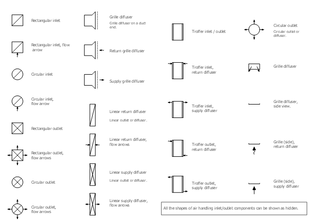
The vector stencil library "HVAC registers, drills and diffusers" contains 47 HVAC symbols of rectangular, circular, linear and troffer air handling inlet/ outlet
components, registers, drills and diffusers.
Use it for drawing HVAC system diagrams, heating, ventilation, air conditioning, refrigeration, automated building control, and environmental control design floor
plans and equipment layouts.
"A ceiling is an overhead interior surface that covers the upper limit of a room. It is not generally considered a structural element, but a finished surface concealing the underside of the floor or roof structure above.
Ceilings are classified according to their appearance or construction. A cathedral ceiling is any tall ceiling area similar to those in a church. A dropped ceiling is one in which the finished surface is constructed anywhere from a few inches to several feet below the structure above it. This may be done for aesthetic purposes, such as achieving a desirable ceiling height; or practical purposes such as providing a space for HVAC or piping. An inverse of this would be a raised floor. A concave or barrel shaped ceiling is curved or rounded, usually for visual or acoustical value, while a coffered ceiling is divided into a grid of recessed square or octagonal panels, also called a "lacunar ceiling". A cove ceiling uses a curved plaster transition between wall and ceiling; it is named for cove molding, a molding with a concave curve." [Ceiling. Wikipedia]
"... reflected Ceiling Plans (RCP)s showing ceiling layouts appear after the floor plans." [Plan (drawing). Wikipedia]
The vector stencils example "Design elements - HVAC registers, drills and diffusers" is included in HVAC Plans solution from the Building Plans area of ConceptDraw Solution Park.
Reflected ceiling plan symbols
- RCP - HVAC layout | HVAC Plans | How to Create a HVAC Plan ...
- HVAC Plans | How to Create a HVAC Plan | Air handler- HVAC plan ...
- HVAC Plans | RCP - HVAC layout | How to Create a HVAC Plan | Hvac
- Hvac Duct Layout Drawing
- HVAC Plans | Aerospace and Transport | Metro Map | Draw The ...
- How to Create a HVAC Plan | Design elements - HVAC ductwork ...
- HVAC Plans | How To Draw Riser Diagram Of Sanitary Building With ...
- Hvac Duct Design Example
- RCP - HVAC layout | How to Create a Reflected Ceiling Floor Plan ...
- Symbol Of Air Duct Grill In Hvac Drawing