This process flow diagram (PFD) of a typical crude oil distillation unit as used in petroleum crude oil refineries was redrawn from Wikipedia file: Crude Oil Distillation Unit.png. [en.wikipedia.org/ wiki/ File:Crude_ Oil_ Distillation_ Unit.png]
This file is licensed under the Creative Commons Attribution-Share Alike 3.0 Unported license. [creativecommons.org/ licenses/ by-sa/ 3.0/ deed.en]
"An oil refinery or petroleum refinery is an industrial process plant where crude oil is processed and refined into more useful products such as petroleum naphtha, gasoline, diesel fuel, asphalt base, heating oil, kerosene and liquefied petroleum gas. Oil refineries are typically large, sprawling industrial complexes with extensive piping running throughout, carrying streams of fluids between large chemical processing units. In many ways, oil refineries use much of the technology of, and can be thought of, as types of chemical plants. The crude oil feedstock has typically been processed by an oil production plant. There is usually an oil depot (tank farm) at or near an oil refinery for the storage of incoming crude oil feedstock as well as bulk liquid products.
An oil refinery is considered an essential part of the midstream side of the petroleum industry." [en.wikipedia.org/ wiki/ Oil_ refinery]
The process flow diagram (PFD) example "Crude oil distillation" was drawn using the ConceptDraw PRO diagramming and vector drawing software extended with the Chemical and Process Engineering solution from the Chemical and Process Engineering area of ConceptDraw Solution Park.
Process flow diagram (PFD)
-crude-oil-distillation-unit---pfd.png--diagram-flowchart-example.png)
The vector stencils library "Plumbing" contains 31 symbols of plumbing components and bathroom fixtures. Use it for dawing plumbing and piping plans, schematic diagrams, blueprints of waste water disposal systems, hot and cold water supply systems in the ConceptDraw PRO diagramming and vector drawing software extended with the Plumbing and Piping Plans solution from the Building Plans area of ConceptDraw Solution Park.
Boiler, flat ends

Boiler, curved ends

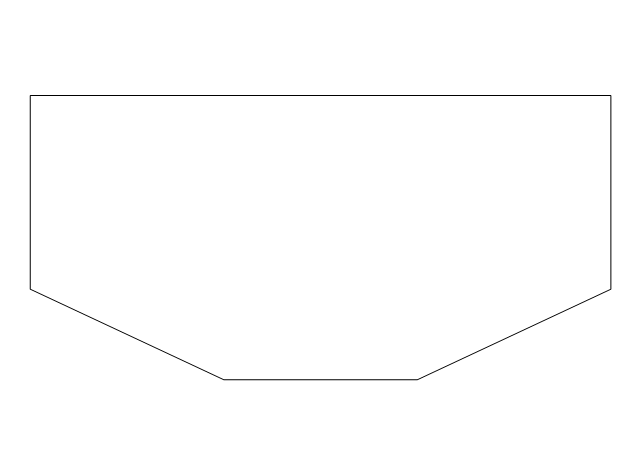
Boiler, angled ends

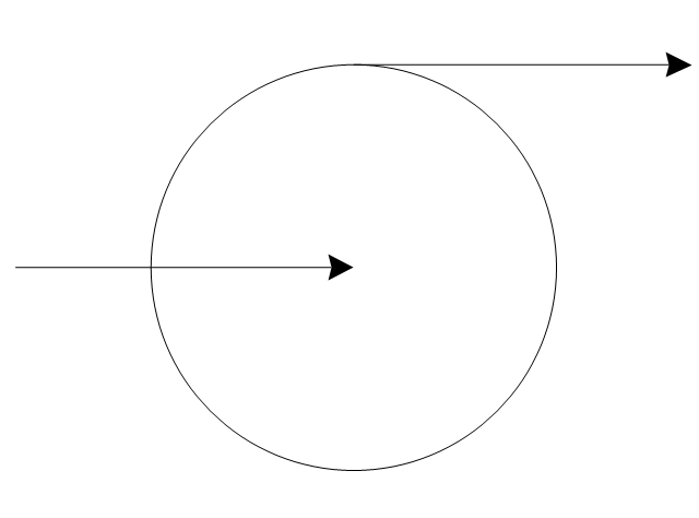
Heating/Cooling coil

Pump
Pump

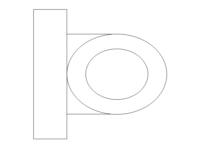
Radiator

Convector

Convector, fan

Radiant panel (plan), sgl
,-sgl-plumbing---vector-stencils-library.png--diagram-flowchart-example.png)
Radiant panel (plan), dbl
,-dbl-plumbing---vector-stencils-library.png--diagram-flowchart-example.png)
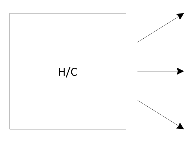
Heater/cooler, horizontal
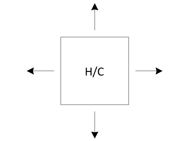
Heater/cooler, downward
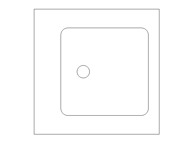
Radiant panel (face)
-plumbing---vector-stencils-library.png--diagram-flowchart-example.png)
Tank, open

Tank, closed

Water surface

Pipe coils

Pipe coils, fins

Pipe coils, break

Pipe coils, break, fins

Sink unit

Basin
Toilet
Bath
Basin (side)
-plumbing---vector-stencils-library.png--diagram-flowchart-example.png)
Toilet (side)
-plumbing---vector-stencils-library.png--diagram-flowchart-example.png)
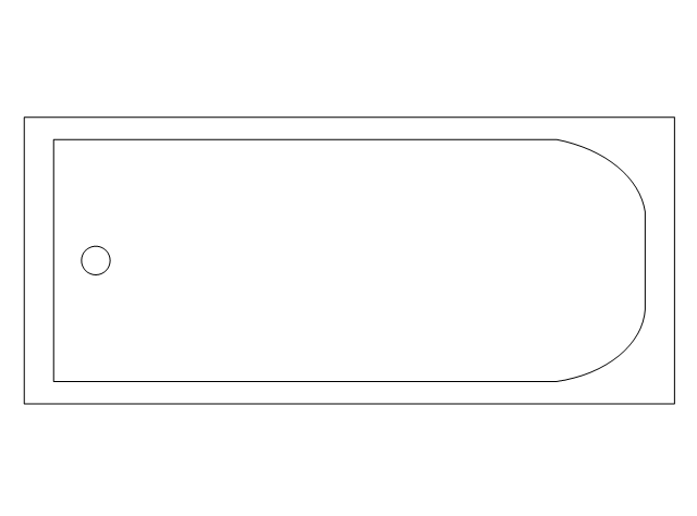
Bath (side)
-plumbing---vector-stencils-library.png--diagram-flowchart-example.png)
End view
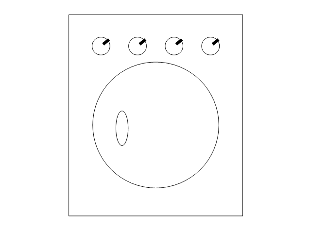
Washing machine
Shower head
Towel rail

The vector stencils library "Chemical engineering" contains 24 symbols of chemical and process engineering equipment.
Use these shapes for drawing Process Flow Diagrams (PFD), Piping and Instrumentation Diagrams (P&ID), and Water Flow Diagrams in the ConceptDraw PRO software extended with the Chemical and Process Engineering solution from the Chemical and Process Engineering area of ConceptDraw Solution Park.
www.conceptdraw.com/ solution-park/ engineering-chemical-process
Clarifier

Screen

Filter

Agitator

Vapor 1

Vapor 2

Vessel

Pump mixer

Centrifugal pump

Fan

Blower

Evaporator

Tower

Flash drum

Roll press

Cooling tower

Tank car

Tank truck

Kettle

Valve

Motor valve

Venturi

Propeller

Instrument

 Fishbone Diagrams
The Fishbone Diagrams solution extends ConceptDraw PRO v10 software with the ability to easily draw the Fishbone Diagrams (Ishikawa Diagrams) to clearly see the cause and effect analysis and also problem solving. The vector graphic diagrams produced using this solution can be used in whitepapers, presentations, datasheets, posters, and published technical material.
 Cafe and Restaurant Floor Plans
Restaurants and cafes are popular places for recreation, relaxation, and are the scene for many impressions and memories, so their construction and design requires special attention. Restaurants must to be projected and constructed to be comfortable and e
- Piping and Instrumentation Diagram Software | Chemical ...
- Piping and Instrumentation Diagram Software | Chemical ...
- Oil Refinary Pipe Line Drawing
- Electrical Symbols, Electrical Diagram Symbols | Chemical ...
- Piping and Instrumentation Diagram Software | HVAC Plans | Pumps ...
- Piping And Instrumentation Diagram Evaporator
- Pipe Line Refinery Drawing
- Diagram Mixing Tank
- Pipe Diagram For Clarifier
- Draw And Labeled A Schematic Diagram Of An Agitator
- How To use Appliances Symbols for Building Plan | Piping and ...
- Piping and Instrumentation Diagram Software | Plumbing and Piping ...
- Design elements - Industrial equipment | Piping and Instrumentation ...
- Vessels - Vector stencils library | Piping and Instrumentation ...
- Diagram Of Tank Press Equipment
- Chemical engineering - Vector stencils library | Vessels - Vector ...
- Simple Flow Chart | Process Flowchart | Piping and Instrumentation ...
- Cisco Buildings. Cisco icons, shapes, stencils and symbols | Piping ...
- Design elements - Industrial equipment | Piping and Instrumentation ...
- Process Flow Diagram Symbols | HVAC control equipment - Vector ...