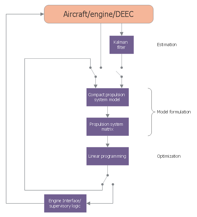
This CFD sample was designed on the base of Wikimedia Commons file: Performance seeking control flow diagram.jpg.
[commons.wikimedia.org/ wiki/ File:Performance_ seeking_ control_ flow_ diagram.jpg]
Source of this CFD is Subsonic Flight Test Evaluationof a Performance Seeking ControlAlgorithm on an F-15 Airplane NASA Technical Memorandum 4400. [nasa.gov/ centers/ dryden/ pdf/ 88262main_ H-1808.pdf]
The CFD example "Control flow diagram - Performance Seeking" was designed using ConceptDraw PRO software extended with Сlassic Business Process Modeling solution from Business Processes area of ConceptDraw Solution Park.
Business process modeling diagram
Used Solutions
This is a schematic process flow diagram of the processes used in a typical oil refinery.
This process flow diagram (PFD) example was redesigned from the Wikimedia Commons file: RefineryFlow.png. [commons.wikimedia.org/ wiki/ File:RefineryFlow.png]
This file is licensed under the Creative Commons Attribution-Share Alike 3.0 Unported license. [creativecommons.org/ licenses/ by-sa/ 3.0/ deed.en]
"An oil refinery or petroleum refinery is an industrial process plant where crude oil is processed and refined into more useful products such as petroleum naphtha, gasoline, diesel fuel, asphalt base, heating oil, kerosene and liquefied petroleum gas. Oil refineries are typically large, sprawling industrial complexes with extensive piping running throughout, carrying streams of fluids between large chemical processing units. In many ways, oil refineries use much of the technology of, and can be thought of, as types of chemical plants. The crude oil feedstock has typically been processed by an oil production plant. There is usually an oil depot (tank farm) at or near an oil refinery for the storage of incoming crude oil feedstock as well as bulk liquid products.
An oil refinery is considered an essential part of the downstream side of the petroleum industry." [Oil refinery. Wikipedia]
The PFD example "Process flow diagram - Typical oil refinery" was created using the ConceptDraw PRO diagramming and vector drawing software extended with the Chemical and Process Engineering solution from the Chemical and Process Engineering area of ConceptDraw Solution Park.
Process Flow Diagram (PFD)
-process-flow-diagram---typical-oil-refinery.png--diagram-flowchart-example.png)
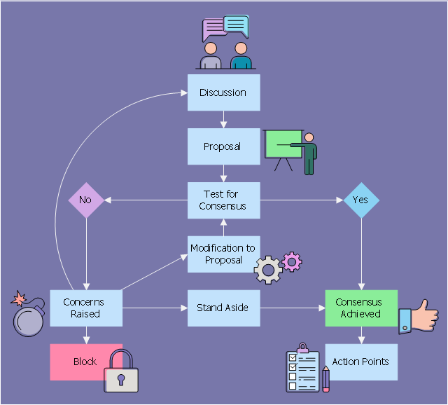
This flowchart example illustrates the consensus based decision-making.
It was designed on the base of Wikimedia Commons file: Consensus flow chart.svg. [commons.wikimedia.org/ wiki/ File:Consensus_ flow_ chart.svg]
"Consensus decision-making is a group decision-making process in which group members develop, and agree to support a decision in the best interest of the whole. Consensus may be defined professionally as an acceptable resolution, one that can be supported, even if not the "favourite" of each individual. ... Consensus decision-making is thus concerned with the process of deliberating and finalizing a decision, and the social, economic, legal, environmental and political effects of applying this process." [Consensus decision-making. Wikipedia]
This file is licensed under the Creative Commons Attribution-Share Alike 3.0 Unported license. [creativecommons.org/ licenses/ by-sa/ 3.0/ deed.en]
The decision diagram example "Consensus flow chart" was designed using ConceptDraw software extended with Decision Making solution from Management area of ConceptDraw Solution Park.
Decision diagram example
Pyramid Diagram

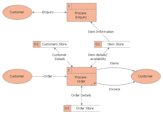
This DFD sample was designed on the base of Wikimedia Commons file: DFD0.png.
"This is a Level 0 Data Flow Diagram for the fictional company "AvisonPlay.com".
[commons.wikimedia.org/ wiki/ File:DFD0.png]
This file is licensed under the Creative Commons Attribution-Share Alike 3.0 Unported license. [creativecommons.org/ licenses/ by-sa/ 3.0/ deed.en]
The DFD example "Data flow diagram - Order" was designed using ConceptDraw PRO software extended with Сlassic Business Process Modeling solution from Business Processes area of ConceptDraw Solution Park.
Business process modeling diagram
Pyramid Diagram

Flowchart on Bank. Flowchart Examples


Create Flowchart

This process flow diagram (PFD) example shows an amine treating system for the removal of gaseous hydrogen sulfide from gas streams. It is used in oil refineries and chemical plants. This PFD sample was redesigned from the Wikimedia Commons file: AmineTreating.png. [commons.wikimedia.org/ wiki/ File:AmineTreating.png]
This file is licensed under the Creative Commons Attribution-Share Alike 3.0 Unported license. [creativecommons.org/ licenses/ by-sa/ 3.0/ deed.en]
"Amine gas treating, also known as gas sweetening and acid gas removal, refers to a group of processes that use aqueous solutions of various alkylamines (commonly referred to simply as amines) to remove hydrogen sulfide (H2S) and carbon dioxide (CO2) from gases. It is a common unit process used in refineries, and is also used in petrochemical plants, natural gas processing plants and other industries.
Processes within oil refineries or chemical processing plants that remove hydrogen sulfide are referred to as "sweetening" processes because the odor of the processed products is improved by the absence of hydrogen sulfide. An alternative to the use of amines involves membrane technology. Membranes are attractive since no reagents are consumed.
Many different amines are used in gas treating:
Diethanolamine (DEA),
Monoethanolamine (MEA),
Methyldiethanolamine (MDEA),
Diisopropanolamine (DIPA),
Aminoethoxyethanol (Diglycolamine) (DGA).
The most commonly used amines in industrial plants are the alkanolamines DEA, MEA, and MDEA. These amines are also used in many oil refineries to remove sour gases from liquid hydrocarbons such as liquified petroleum gas (LPG)." [Amine gas treating. Wikipedia]
The PFD example "Amine treating unit schematic diagram" was drawn using the ConceptDraw PRO diagramming and vector drawing software extended with the Chemical and Process Engineering solution from the Chemical and Process Engineering area of ConceptDraw Solution Park.
Process Flow Diagram (PFD)
-amine-treating-unit-schematic-diagram.png--diagram-flowchart-example.png)
Flowchart. What is Flowchart

- Process flow diagram - Typical oil refinery | Modular Refinery ...
- Well Label Diagram Of Crude Distillation Unit
- Crude oil distillation unit - PFD | Process flow diagram (PFD ...
- Lead to opportunity sales flow | Process flow diagram - Typical oil ...
- People | Lead to opportunity sales flow | Workflow Wiki
- Process flow diagram - Typical oil refinery | Crude oil distillation unit ...
- Amine treating unit schematic diagram | Process flow diagram ...
- Oil And Gas Industry Process Flow Diagrams
- Process Of Human Resources Planning Wikipedia With Diagram
- Oil And Gas Process Flow Diagram