"Smaller mobile devices such as PDAs and smartphones typically use the WIMP elements with different unifying metaphors, due to constraints in space and available input devices. Applications for which WIMP is not well suited may use newer interaction techniques, collectively named as post-WIMP user interfaces.
As of 2011, some touch-screen-based operating systems such as Apple's iOS (iPhone) and Android use the class of GUIs named post-WIMP. These support styles of interaction using more than one finger in contact with a display, which allows actions such as pinching and rotating, which are unsupported by one pointer and mouse." [Graphical user interface. Wikipedia]
"In computing post-WIMP comprises work on user interfaces, mostly graphical user interfaces, which attempt to go beyond the paradigm of windows, icons, menus and a pointing device, i.e. WIMP interfaces. ...
However WIMP interfaces are not optimal for working with complex tasks such as computer-aided design, working on large amounts of data simultaneously, or interactive games. WIMPs are usually pixel-hungry, so given limited screen real estate they can distract attention from the task at hand. Thus, custom interfaces can better encapsulate workspaces, actions, and objects for specific complex tasks. Applications for which WIMP is not well suited include those requiring continuous input signals, showing 3D models, or simply portraying an interaction for which there is no defined standard widget.
Interfaces based on these considerations, now called "post-WIMP", have made their way to the general public. Examples include the interface of the classic MP3 player iPod and a bank's automated teller machine screen." [Post-WIMP. Wikipedia]
The example "iPhone OS (iOS) graphic user interface (GUI) - Activity indicator view" was created using the ConceptDraw PRO diagramming and vector drawing software extended with the Graphic User Interface solution from the Software Development area of ConceptDraw Solution Park.
iPhone GUI
-graphic-user-interface-(gui)---activity-indicator-view.png--diagram-flowchart-example.png)
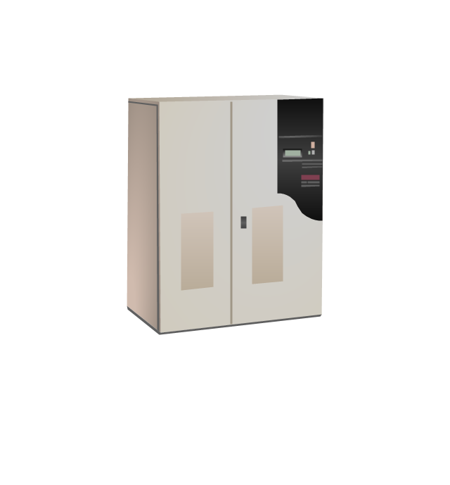
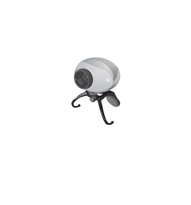
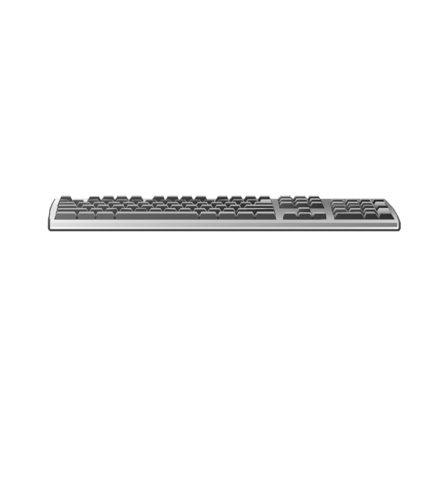
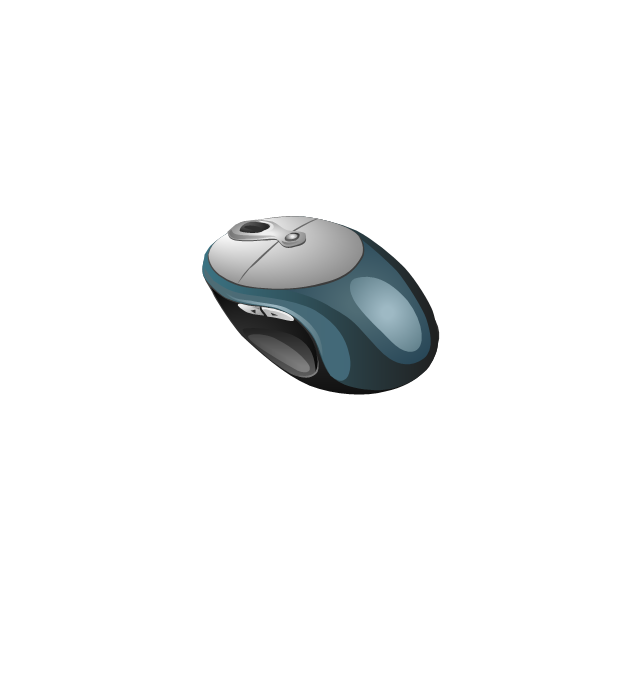
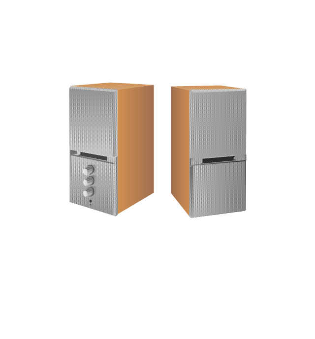
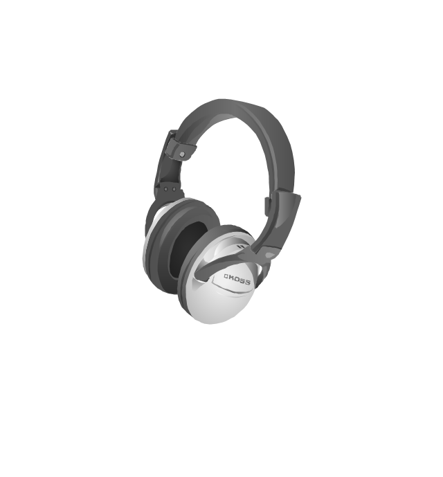
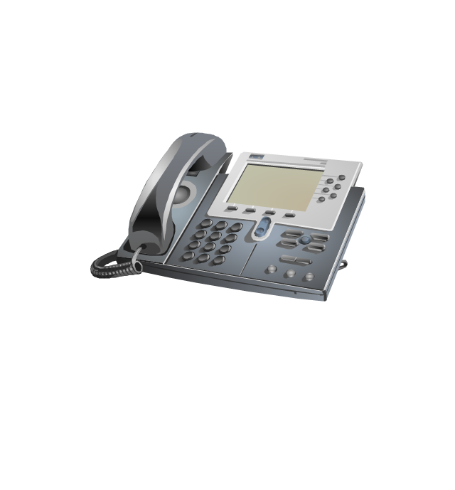
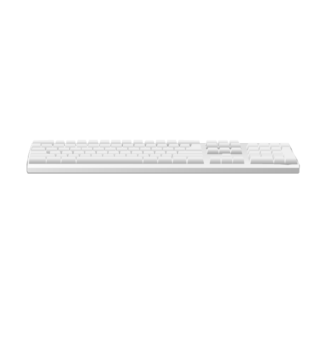
The vector stencils library "Computer peripheral devices" contains 18 clipart images of computer peripheral devices and equipment for drawing network diagrams.
"A peripheral is a device that is connected to a host computer, but not an integral part of it. It expands the host's capabilities but does not form part of the core computer architecture. It is often, but not always, partially or completely dependent on the host.
There are three different types of peripherals:
(1) Input, used to interact with, or send data to the computer (mouse, keyboards, etc.).
(2) Output, which provides output to the user from the computer (monitors, printers, etc.).
(3) Storage, which stores data processed by the computer (hard drives, flash drives, etc.)" [Peripheral. Wikipedia]
The clip art example "Computer peripheral devices - Vector stencils library" was created using the ConceptDraw PRO diagramming and vector drawing software extended with the Computer and Networks solution from the Computer and Networks area of ConceptDraw Solution Park.
Uninterruptible power supply
Webcam
Keyboard
Optical mouse
Computer speakers
Headphones
VoIP phone
Apple Keyboard
Apple Mouse
LCD projector
Port adapter
Airport Express
Joystick
Webcam
Video projector
The vector stencils library "Transformers and windings" contains 29 element symbols of transformers, windings, couplers, metering devices, transductors, magnetic cores, chokes, and a variometer.
Use it to design the electromechanical device schematics and electronic circuit diagrams.
"A transformer is an electrical device that transfers energy between two circuits through electromagnetic induction. Transformers may be used in step-up or step-down voltage conversion, which 'transforms' an AC voltage from one voltage level on the input of the device to another level at the output terminals. This special function of transformers can provide control of specified requirements of current level as an alternating current source, or it may be used for impedance matching between mismatched electrical circuits to effect maximum power transfer between the circuits.
A transformer most commonly consists of two windings of wire that are wound around a common core to induce tight electromagnetic coupling between the windings. The core material is often a laminated iron core. The coil that receives the electrical input energy is referred to as the primary winding, while the output coil is called the secondary winding.
An alternating electric current flowing through the primary winding (coil) of a transformer generates an electromagnetic field in its surroundings and a varying magnetic flux in the core of the transformer. By electromagnetic induction this magnetic flux generates a varying electromotive force in the secondary winding, resulting in a voltage across the output terminals. If a load impedance is connected across the secondary winding, a current flows through the secondary winding drawing power from the primary winding and its power source." [Transformer. Wikipedia]
"An electromagnetic coil (or simply a "coil") is formed when a conductor is wound around a core or form to create an inductor or electromagnet. When electricity is passed through a coil, it generates a magnetic field. One loop of wire is usually referred to as a turn or a winding, and a coil consists of one or more turns. For use in an electronic circuit, electrical connection terminals called taps are often connected to a coil. Coils are often coated with varnish or wrapped with insulating tape to provide additional insulation and secure them in place. A completed coil assembly with one or more set of coils and taps is often called the windings.
Windings are used in transformers, electric motors, inductors, solenoids, loudspeakers, and many other applications." [Electromagnetic coil. Wikipedia]
The shapes example "Design elements - Transformers and windings" was drawn using the ConceptDraw PRO diagramming and vector drawing software extended with the Electrical Engineering solution from the Engineering area of ConceptDraw Solution Park.
Transformer and winding symbols

The vector stencils library "Delay elements" contains 12 symbols of delay elements for drawing electrical schematics and electronic circuit diagrams.
"An analog delay line is a network of electrical components connected in series, where each individual element creates a time difference or phase change between its input signal and its output signal. It operates on analog signals whose amplitude varies continuously. An example is a bucket-brigade device. Other types of delay line include acoustic, magnetostrictive, and surface acoustic wave devices. A series of RC networks can be cascaded to form a delay. A long transmission line can also provide a delay element. The delay time of an analog delay line may be only a few nanoseconds or several milliseconds, limited by the practical size of the physical medium used to delay the signal and the propagation speed of impulses in the medium." [Analog delay line. Wikipedia]
The symbols example "Design elements - Delay elements" was drawn using the ConceptDraw PRO diagramming and vector drawing software extended with the Electrical Engineering solution from the Engineering area of ConceptDraw Solution Park.
Delay element symbols

- Examples Of Wireless Input Devices
- Example Of Input Device
- Input Device Joystick Clipart
- Computer Input Device Example
- Computer Input Devices Examples
- Control devices - Vector stencils library | Example Of Trackball In ...
- Examples Of Input Devices
- Input Devices
- Examples Of Input Devices Of Computer
- Mobile Input Devices Examples
- Local area network (LAN). Computer and Network Examples ...
- Design elements - Computer peripheral devices | Control devices ...
- Control devices - Vector stencils library | Control devices - Vector ...
- Examples Of The Computer Input Devices
- Input Device Of Computer Clipart
- Network Glossary Definition | Input Example Picture Of Joystick ...
- Control devices - Vector stencils library | Network Glossary Definition ...
- All Input Devices Of Computer In Complete Chart
- Example Peripheral Devices