How To use Switches in Network Diagram


Network Layout

This cafe electrical floor plan sample shows the outlet and switch layout.
"An electrical drawing, is a type of technical drawing that shows information about power, lighting, and communication for an engineering or architectural project. Any electrical working drawing consists of "lines, symbols, dimensions, and notations to accurately convey an engineering's design to the workers, who install the electrical system on the job".
A complete set of working drawings for the average electrical system in large projects usually consists of:
(1) A plot plan showing the building's location and outside electrical wiring.
(2) Floor plans showing the location of electrical systems on every floor.
(3) Power-riser diagrams showing panel boards.
(4) Control wiring diagrams.
(5) Schedules and other information in combination with construction drawings.
Electrical drafters prepare wiring and layout diagrams used by workers who erect, install, and repair electrical equipment and wiring in communication centers, power plants, electrical distribution systems, and buildings." [Electrical drawing. Wikipedia]
The outlet and switch layout example "Cafe electrical floor plan" was created using the ConceptDraw PRO diagramming and vector drawing software extended with the Electric and Telecom Plans solution from the Building Plans area of ConceptDraw Solution Park.
Outlet and switch layout

Network Hubs

The vector stencils library "Switches" contains 25 symbols of electrical and light switches and breakers.
"In electrical engineering, a switch is an electrical component that can break an electrical circuit, interrupting the current or diverting it from one conductor to another.
The most familiar form of switch is a manually operated electromechanical device with one or more sets of electrical contacts, which are connected to external circuits.
A switch may be directly manipulated by a human as a control signal to a system, ... or to control power flow in a circuit, such as a light switch. Automatically operated switches can be used to control the motions of machines, for example, to indicate that a garage door has reached its full open position or that a machine tool is in a position to accept another workpiece. Switches may be operated by process variables such as pressure, temperature, flow, current, voltage, and force, acting as sensors in a process and used to automatically control a system. For example, a thermostat is a temperature-operated switch used to control a heating process. A switch that is operated by another electrical circuit is called a relay." [Switch. Wikipedia]
Use the design elements library "Switches" for drawing light switches layouts, electrical and telecommunication equipment floor plans for building design and construction using the ConceptDraw PRO diagramming and vector drawing software.
The shapes library "Switches" is included in the Electric and Telecom Plans solution from the Building Plans area of ConceptDraw Solution Park.
Electrical switch symbols

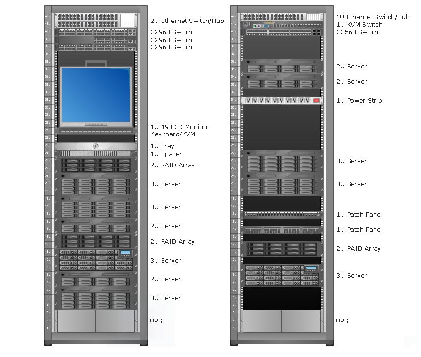
Rack Diagrams
- Drawing Of Switches In Computer
- Lighting and switch layout | Reflected ceiling plan | Classroom ...
- How To use Switches in Network Diagram | Computer network ...
- Drawing For Electrical Switch
- Building Drawing Design Element Site Plan | Interior Design ...
- VMware vNetwork Distributied Switch (vDS). Computer and Network ...
- Design elements - Switches and relays | Overload Symbol For ...
- Lighting and switch layout | How To use House Electrical Plan ...
- How To use House Electrical Plan Software | Building Drawing ...
- Mechanical Drawing Symbols | Design elements - Fluid power ...
- Cisco switches and hubs - Vector stencils library | Network Diagram ...
- How To use House Electrical Plan Software | Cafe electrical floor ...
- Cisco Switches and Hubs. Cisco icons, shapes, stencils and symbols
- How To use House Electrical Plan Software | Electrical Drawing ...
- Sign For A Light Switch In Plan Drawing
- Switch Diagram In Computer Communication
- How To use House Electrical Plan Software | Lighting and switch ...
- Wide area network (WAN) topology. Computer and Network Examples
- How To use House Electrical Plan Software | Electrical Drawing ...
- Electrical Drawing Software and Electrical Symbols | Design ...