 Electrical Engineering
This solution extends ConceptDraw PRO v.9.5 (or later) with electrical engineering samples, electrical schematic symbols, electrical diagram symbols, templates and libraries of design elements, to help you design electrical schematics, digital and analog
 Computers and Communications
Computers and communications solution extends ConceptDraw PRO software with illustration samples, templates and vector stencils libraries with clip art of computers, control devices, communications, technology, Apple machines.
 Germany Map
The Germany Map solution contains collection of samples, templates and scalable vector stencil graphic maps, representing map of Germany and all 16 states of Germany. Use the Germany Map solution from ConceptDraw Solution Park as the base for various them
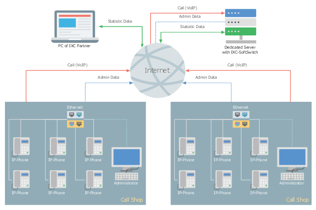
This telecom diagram sample illustrates the call shop solution. It was designed on the base of the Wikimedia Commons file: Call shops.jpg.
[commons.wikimedia.org/ wiki/ File:Call_ shops.jpg]
This file is licensed under the Creative Commons Attribution-Share Alike 3.0 Unported license. [creativecommons.org/ licenses/ by-sa/ 3.0/ deed.en]
"A call shop is a business providing on-site access to telephones for long-distance calling in countries without widespread home long-distance service. Calls may be prepaid or postpaid." [Call shop. Wikipedia]
The telecommunication diagram example "Call shop solution" was created using the ConceptDraw PRO diagramming and vector drawing software extended with the Computers and Communications solution from the Illustration area of ConceptDraw Solution Park.
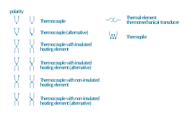
The vector stencils library "Thermo" contains 14 symbols of thermoelectric elements: thermal element, thermocouples with and without heating elements, thermoplile.
Use it for drawing electrical layouts, electronic schematics, and circuit diagrams.
"The thermoelectric effect is the direct conversion of temperature differences to electric voltage and vice versa. A thermoelectric device creates voltage when there is a different temperature on each side. Conversely, when a voltage is applied to it, it creates a temperature difference. At the atomic scale, an applied temperature gradient causes charge carriers in the material to diffuse from the hot side to the cold side.
This effect can be used to generate electricity, measure temperature or change the temperature of objects. Because the direction of heating and cooling is determined by the polarity of the applied voltage, thermoelectric devices can be used as temperature controllers.
The term "thermoelectric effect" encompasses three separately identified effects: the Seebeck effect, Peltier effect, and Thomson effect. Textbooks may refer to it as the Peltier–Seebeck effect. ...
Thermocouples and thermopiles are devices that use the Seebeck effect to measure the temperature difference between two objects, one connected to a voltmeter and the other to the probe. The temperature of the voltmeter, and hence that of the material being measured by the probe, can be measured separately using cold junction compensation techniques." [Thermoelectric effect. Wikipedia]
The shapes example "Design elements - Thermo" was drawn using the ConceptDraw PRO diagramming and vector drawing software extended with the Electrical Engineering solution from the Engineering area of ConceptDraw Solution Park.
Design Element: Rack Diagram for Network Diagrams
ConceptDraw PRO is perfect for software designers and software developers who need to draw Rack Diagrams.
- Lighting and switch layout | Design elements - Electrical and telecom
- Electrical Drawing Software | How To use House Electrical Plan ...
- How To use House Electrical Plan Software | Cafe electrical floor ...
- How To use House Electrical Plan Software | CAD Drawing Software ...
- Wiring Diagram Floor Software | How To use House Electrical Plan ...
- How To use House Electrical Plan Software | Electrical Drawing ...
- How To use House Electrical Plan Software | Building Drawing ...
- How To use House Electrical Plan Software
- Technical Drawing Software | How To use House Electrical Plan ...
- Plant Layout Plans | Design elements - Stations | Mechanical ...
- Design elements - Stations | Plant Layout Plans | Electrical and ...
- Interior Design Office Layout Plan Design Element | Design ...
- Plumbing and Piping Plans | Building Drawing Design Element ...
- How To use House Electrical Plan Software | How To use Electrical ...
- How To use House Electrical Plan Software | Electrical and Telecom ...
- Planning Nd Layout Installtion Of Electricity In Building
- How To use House Electrical Plan Software | How To Draw Building ...
- How To use House Electrical Plan Software | Design elements ...
- Design elements - Electrical and telecom | Electrical Drawing ...
- How To use House Electrical Plan Software | How to Create an ...


.png)