ConceptDraw Arrows10 Technology

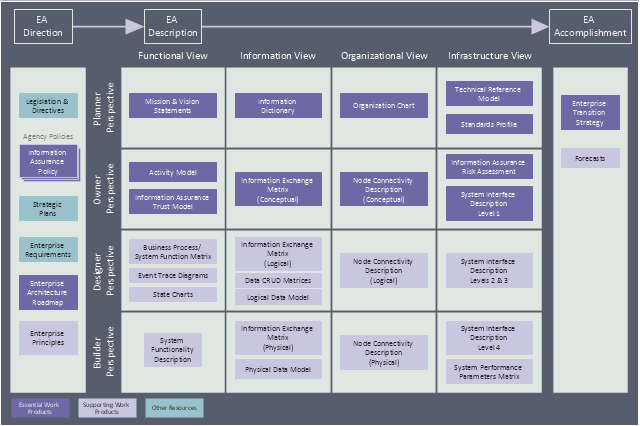
This enterprise architecture diagram sample was redesigned from the Wikipedia file: TEAF Work Products for EA Direction, Description, and Accomplishment.jpg. [en.wikipedia.org/ wiki/ File:TEAF_ Work_ Products_ for_ EA_ Direction,_ Description,_ and_ Accomplishment.jpg]
"Treasury Enterprise Architecture Framework (TEAF) was an Enterprise architecture framework for treasury, based on the Zachman Framework. It was developed by the US Department of the Treasury and published in July 2000. May 2012 this framework has been subsumed by evolving Federal Enterprise Architecture Policy as documented in "The Common Approach to Federal Enterprise Architecture".
The material presented here is obsolete and only useful for historical reference and is not the current policy in use by the Department of the Treasury." [en.wikipedia.org/ wiki/ Treasury_ Enterprise_ Architecture_ Framework]
The enterprise architecture diagram example "Resources and TEAF Work Products for EA Direction, Description, and Accomplishment" was created using the ConceptDraw PRO diagramming and vector drawing software extended with the Enterprise Architecture Diagrams solution from the Management area of ConceptDraw Solution Park.
Enterprise architecture diagram
HelpDesk
How to Resize Objects Disproportionately in ConceptDraw PRO

The circuit diagram example "Bipolar current mirror" was redesigned from the Wikipedia file: Current mirror.png.
[en.wikipedia.org/ wiki/ File:Current_ mirror.png]
This file is licensed under the Creative Commons Attribution-Share Alike 3.0 Unported license. [creativecommons.org/ licenses/ by-sa/ 3.0/ deed.en]
"A current mirror is a circuit designed to copy a current through one active device by controlling the current in another active device of a circuit, keeping the output current constant regardless of loading. The current being 'copied' can be, and sometimes is, a varying signal current. Conceptually, an ideal current mirror is simply an ideal inverting current amplifier that reverses the current direction as well or it is a current-controlled current source (CCCS). The current mirror is used to provide bias currents and active loads to circuits. ...
Basic BJT current mirror.
If a voltage is applied to the BJT base-emitter junction as an input quantity and the collector current is taken as an output quantity, the transistor will act as an exponential voltage-to-current converter. By applying a negative feedback (simply joining the base and collector) the transistor can be "reversed" and it will begin acting as the opposite logarithmic current-to-voltage converter; now it will adjust the "output" base-emitter voltage so as to pass the applied "input" collector current.
The simplest bipolar current mirror ... implements this idea. It consists of two cascaded transistor stages acting accordingly as a reversed and direct voltage-to-current converters." [Current mirror. Wikipedia]
The circuit diagram example "Bipolar current mirror" was created using the ConceptDraw PRO diagramming and vector drawing software extended with the Electrical Engineering solution from the Engineering area of ConceptDraw Solution Park.
Circuit diagram

HelpDesk
How to Create a Data Flow Diagram using ConceptDraw PRO
 example")
Garrett IA Diagrams with ConceptDraw PRO

- Diagram Of Direction Map
- Maps and Directions | Map Directions | Sign Making Software | Road ...
- Direction In Management Diagram
- Employment Form Software | Employment policy direction ...
- A Flow Diagram Of Direction
- Map Directions | UML Composite Structure Diagram | Sign Making ...
- Direction Valvu And Professional Valve Electrical Diagram
- Direction Map Diagram
- Directional Maps | 3D Network Diagram Software | Maps and ...
- Bubble diagram - Employment policy direction
- Entity Relationship Diagram Symbols | Electrical Symbols, Electrical ...
- Maps Driving Directions | Entity-Relationship Diagram (ERD) with ...
- Sign Making Software | Directional Maps | Map Directions | Show ...
- Enterprise Architecture Diagrams | How to Create an Enterprise ...
- Management Direction Diagrams
- Road signs - Vector stencils library | Map Directions | Maps and ...
- Example of Flowchart Diagram | Maps and Directions | Maps Driving ...
- Maps and Directions | Map Directions | Road signs - Vector stencils ...
- Employment policy direction | Best Diagramming Software for Mac ...
- Maps and Directions | Sign Making Software | Map Directions ...