This SysML package diagram example was redesigned from the Wikimedia Commons file: Deployment Model Structure.PNG.
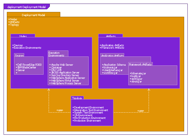
"Packages containing nodes and artifacts."
[commons.wikimedia.org/ wiki/ File:Deployment_ Model_ Structure.PNG]
This file is licensed under the Creative Commons Attribution-Share Alike 3.0 Unported license. [creativecommons.org/ licenses/ by-sa/ 3.0/ deed.en]
"Package diagrams can use packages containing use cases to illustrate the functionality of a software system.
Package diagrams can use packages that represent the different layers of a software system to illustrate the layered architecture of a software system. The dependencies between these packages can be adorned with labels / stereotypes to indicate the communication mechanism between the layers.
When To Use
- It is used in large scale systems to picture dependencies between major elements in the system
- Package diagrams represent a compile time grouping mechanism." [Package diagram. Wikipedia]
The example "Package diagram - Deployment model structure" was drawn using the ConceptDraw PRO diagramming and vector drawing software extended with the SysML solution from the Software Development area of ConceptDraw Solution Park.
SysML package diagram
Cloud Computing Architecture Diagrams

UML Use Case Diagram Example. Services UML Diagram. ATM system

Design Elements for UML Diagrams

Cross-Functional Flowchart


UML Timing Diagram, Design Elements

UML in 10 mins

UML Collaboration Diagram. Design Elements

Diagramming Software for Design UML Collaboration Diagrams


Material Requisition Flowchart. Flowchart Examples

- UML Deployment Diagram . Diagramming Software for Design UML ...
- Uml Diagrams Wikipedia
- Difference Between Component And Deployment Diagram
- Rapid UML | UML deployment diagram | Design elements - Bank ...
- UML Deployment Diagram . Design Elements
- Use Case Diagram For Banking System Wiki
- Package diagram - Deployment model structure | Design elements ...
- Wiki Uml Diagrams
- Grid computing system architecture | Computer Network Diagrams ...
- Object Oriented Dfd Wiki