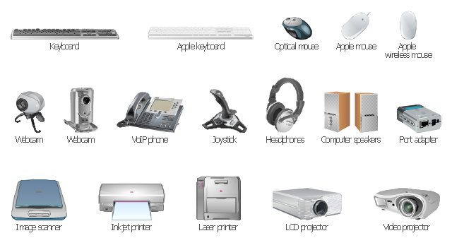
The vector stencils library "Computer peripheral devices" contains 18 clipart images of computer peripheral devices and equipment for drawing network diagrams.
"A peripheral is a device that is connected to a host computer, but not an integral part of it. It expands the host's capabilities but does not form part of the core computer architecture. It is often, but not always, partially or completely dependent on the host.
There are three different types of peripherals:
(1) Input, used to interact with, or send data to the computer (mouse, keyboards, etc.).
(2) Output, which provides output to the user from the computer (monitors, printers, etc.).
(3) Storage, which stores data processed by the computer (hard drives, flash drives, etc.)" [Peripheral. Wikipedia]
The clip art example "Computer peripheral devices - Vector stencils library" was created using the ConceptDraw PRO diagramming and vector drawing software extended with the Computer and Networks solution from the Computer and Networks area of ConceptDraw Solution Park.
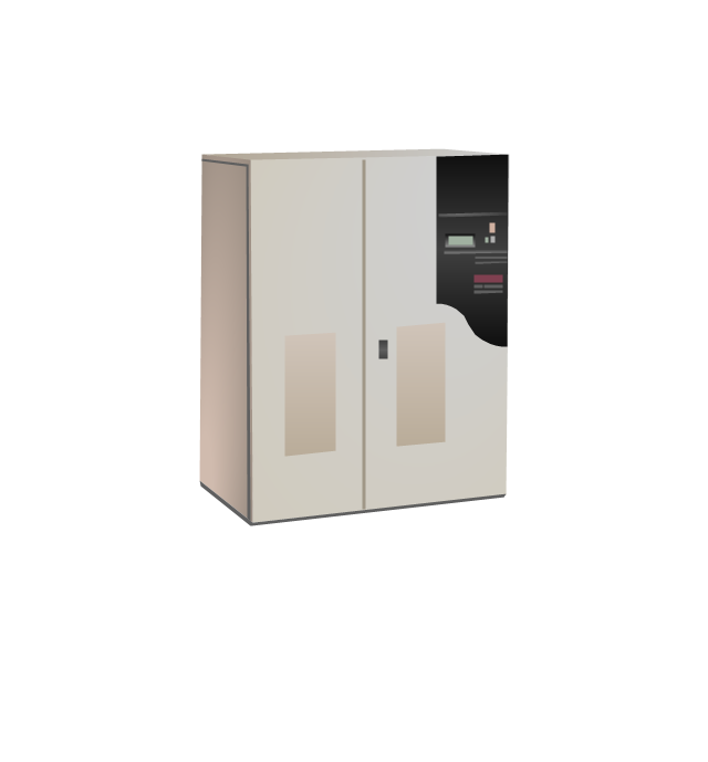
Uninterruptible power supply
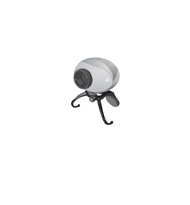
Webcam
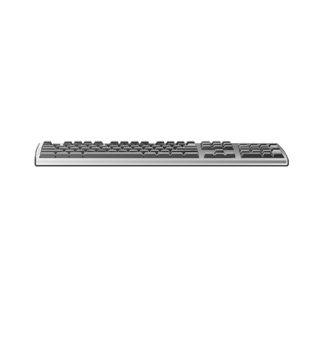
Keyboard
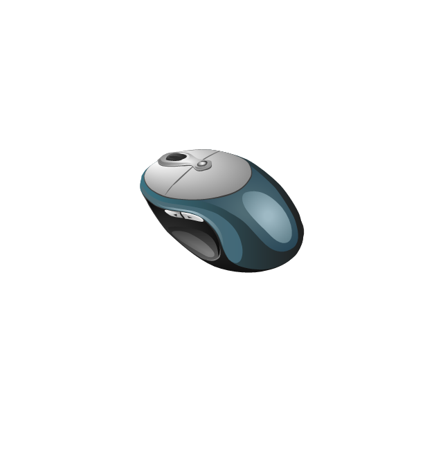
Optical mouse
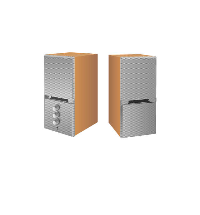
Computer speakers
Headphones

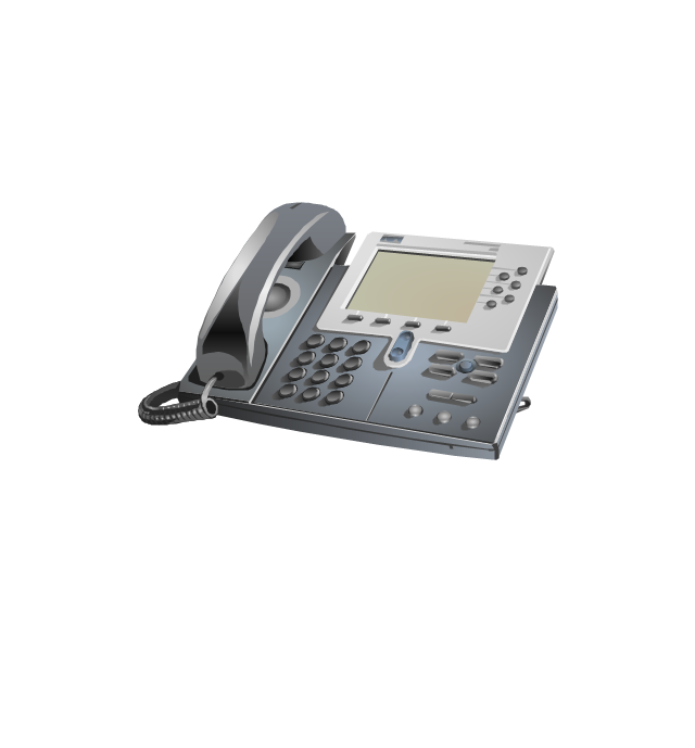
VoIP phone
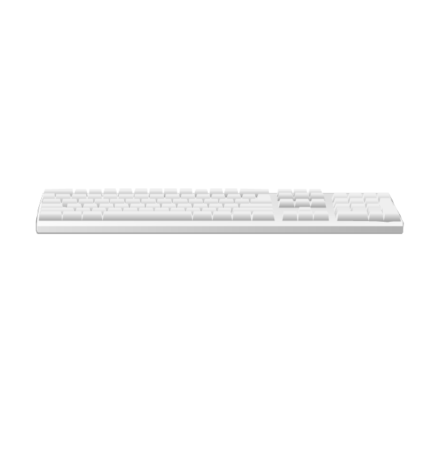
Apple Keyboard
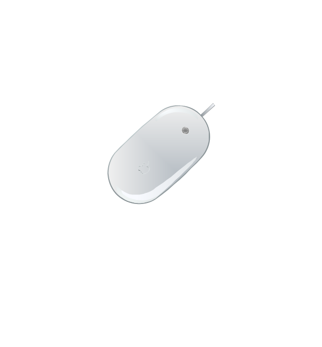
Apple Mouse
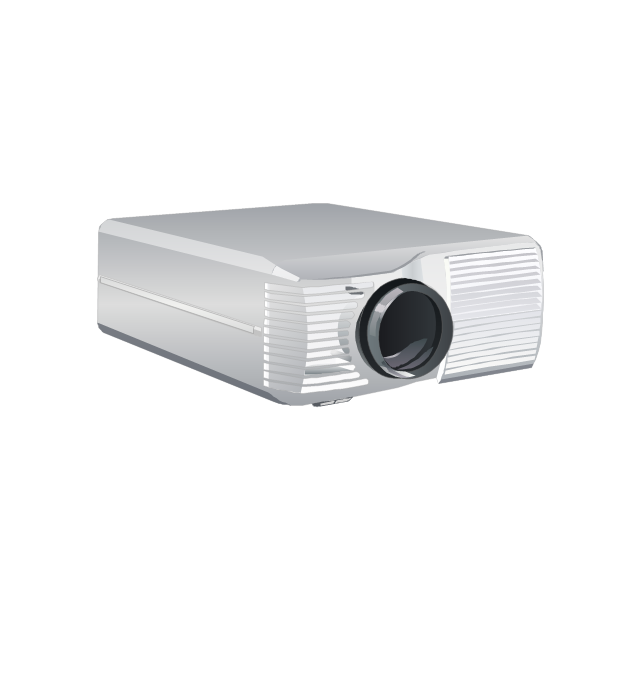
LCD projector
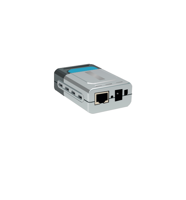
Port adapter
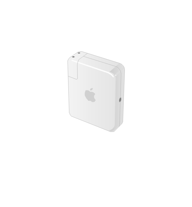
Airport Express
Joystick

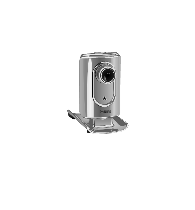
Webcam
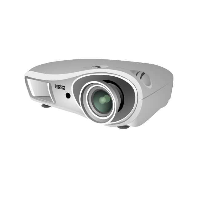
Video projector
The vector stencils library "Cisco switches and hubs" contains 26 symbols of Cisco switches and hubs for drawing computer network diagrams.
"A switch is a device used on a computer network to physically connect devices together. Multiple cables can be connected to a switch to enable networked devices to communicate with each other. Switches manage the flow of data across a network by only transmitting a received message to the device for which the message was intended. Each networked device connected to a switch can be identified using a MAC address, allowing the switch to regulate the flow of traffic. This maximises security and efficiency of the network. Because of these features, a switch is often considered more "intelligent" than a network hub. Hubs neither provide security, or identification of connected devices. This means that messages have to be transmitted out of every port of the hub, greatly degrading the efficiency of the network." [Network switch. Wikipedia]
"An Ethernet hub, active hub, network hub, repeater hub, multiport repeater or hub is a device for connecting multiple Ethernet devices together and making them act as a single network segment. It has multiple input/ output (I/ O) ports, in which a signal introduced at the input of any port appears at the output of every port except the original incoming. A hub works at the physical layer (layer 1) of the OSI model. The device is a form of multiport repeater. Repeater hubs also participate in collision detection, forwarding a jam signal to all ports if it detects a collision." [Ethernet hub. Wikipedia]
The symbols example "Cisco switches and hubs - Vector stencils library" was created using the ConceptDraw PRO diagramming and vector drawing software extended with the Cisco Network Diagrams solution from the Computer and Networks area of ConceptDraw Solution Park.
www.conceptdraw.com/ solution-park/ computer-networks-cisco
Cisco hub

100BaseT hub

Small hub

Workgroup switch

Workgroup switch, subdued

Voice-enabled workgroup switch

ATM switch

LAN2LAN switch

ISDN switch

MGX 8000 multiservice switch

Multilayer switch with Si

Multilayer switch

Multilayer switch with Si, subdued

Program switch

Data center switch

Voice-enabled ATM switch

IP DSL switch

Content switch

Content service switch 1100

Virtual layer switch

Layer 2 remote switch

Server switch

Multilayer remote switch

Multifabric server switch

Access gateway

Long-Reach CPE

The vector stencils library "Computer peripheral devices" contains 20 icon symbols of computer peripheral devices.
Use these equipment shapes for drawing network diagrams.
This clipart library for the ConceptDraw PRO diagramming and vector drawing software is included in the Computer and Networks solution from the Computer and Networks area of ConceptDraw Solution Park.
Use these equipment shapes for drawing network diagrams.
This clipart library for the ConceptDraw PRO diagramming and vector drawing software is included in the Computer and Networks solution from the Computer and Networks area of ConceptDraw Solution Park.
Computer peripheral devices
"Fault-tolerant computer systems are systems designed around the concepts of fault tolerance. In essence, they have to be able to keep working to a level of satisfaction in the presence of faults. ...
Most fault-tolerant computer systems are designed to be able to handle several possible failures, including hardware-related faults such as hard disk failures, input or output device failures, or other temporary or permanent failures; software bugs and errors; interface errors between the hardware and software, including driver failures; operator errors, such as erroneous keystrokes, bad command sequences, or installing unexpected software; and physical damage or other flaws introduced to the system from an outside source." [Fault-tolerant computer system. Wikipedia]
The computer network diagram example "Cisco LAN fault-tolerance system" was created using the ConceptDraw PRO diagramming and vector drawing software extended with the Cisco Network Diagrams solution from the Computer and Networks area of ConceptDraw Solution Park.
LAN fault-tolerance system

Used Solutions
This pinout diagram example showing a VGA connector (as viewed from the socket) was redesigned from the Wikimedia Commons file: DE15 Connector Pinout.svg. [commons.wikimedia.org/ wiki/ File:DE15_ Connector_ Pinout.svg]
"A Video Graphics Array (VGA) connector is a three-row 15-pin DE-15 connector. The 15-pin VGA connector is found on many video cards, computer monitors, and high definition television sets. On laptop computers or other small devices, a mini-VGA port is sometimes used in place of the full-sized VGA connector.
DE-15 is also conventionally called RGB connector, D-sub 15, mini sub D15, mini D15, DB-15, HDB-15, HD-15 or HD15 (High Density, to distinguish it from the older and less flexible DE-9 connector used on some older VGA cards, which has the same shell size but only two rows of pins).
VGA connectors and cables carry analog component RGBHV (red, green, blue, horizontal sync, vertical sync) video signals, and VESA Display Data Channel (VESA DDC) data. In the original version of DE-15 pinout, one pin was keyed by plugging the female connector hole; this prevented non-VGA 15 pin cables from being plugged into a VGA socket. Four pins carried Monitor ID bits which were rarely used; VESA DDC redefined some of these pins and replaced the key pin with +5 V DC power supply.
The VGA interface is not engineered to be hotpluggable (so that the user can connect or disconnect the output device while the host is running), although in practice this can be done and usually does not cause damage to the hardware or other problems. However, nothing in the design ensures that the ground pins make a connection first and break last, so hotplugging may introduce surges in signal lines which may or may not be adequately protected against. Also, depending on the hardware and software, detecting a monitor being connected might not work properly in all cases." [VGA connector. Wikipedia]
The pinout diagram example "VGA connector pinout" was created using the ConceptDraw PRO diagramming and vector drawing software extended with the Audio and Video Connectors solution from the Engineering area of ConceptDraw Solution Park.
VGA connector pinout

 What are Infographics Area
Solutions of the area What is Infographics from ConceptDraw Solution Park collect templates, samples and vector stencils libraries with design elements for the drawing information graphics.
- Input And Output Devices Of Computer Sketch
- Computer Output Devices Drawing Projector
- Sketch Of Output Devices Examples
- Computer peripheral devices - Vector stencils library | How To Print ...
- Computer peripheral devices - Vector stencils library | Wiring ...
- Output Devices Examples
- Sketch Diagram Of Output Devices Of Computer
- Sketch Of Input And Output Devices In Computer
- Input And Output Devices
- Sketched Input And Output Devices
- Input Output Devices
- Example Of Computer Input Devices
- Computer Input And Output Device Scatch
- Computer peripheral devices - Vector stencils library | Design ...
- Flow Chart Of Any Input And Output Device
- Input Output Outlet Symbol
- Lcd Projection Panel As Output Device
- Examples Of The Computer Input Devices
- Examples Of Computer Input Device
- Input Device With Working Diagrams