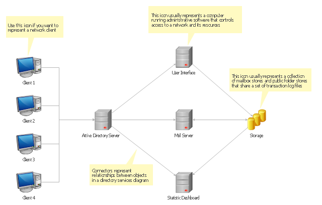
"The client–server model of computing is a distributed application structure that partitions tasks or workloads between the providers of a resource or service, called servers, and service requesters, called clients. Often clients and servers communicate over a computer network on separate hardware, but both client and server may reside in the same system. A server host runs one or more server programs which share their resources with clients. A client does not share any of its resources, but requests a server's content or service function. Clients therefore initiate communication sessions with servers which await incoming requests.
Examples of computer applications that use the client–server model are Email, network printing, and the World Wide Web." [Client–server model. Wikipedia]
The UML communication diagram example "Client server access" was created using the ConceptDraw PRO diagramming and vector drawing software extended with the Rapid UML solution from the Software Development area of ConceptDraw Solution Park.
UML communication diagram

Diagramming Software for Design UML Collaboration Diagrams


"The client–server model of computing is a distributed application structure that partitions tasks or workloads between the providers of a resource or service, called servers, and service requesters, called clients. Often clients and servers communicate over a computer network on separate hardware, but both client and server may reside in the same system. A server host runs one or more server programs which share their resources with clients. A client does not share any of its resources, but requests a server's content or service function. Clients therefore initiate communication sessions with servers which await incoming requests.
Examples of computer applications that use the client–server model are Email, network printing, and the World Wide Web." [Client–server model. Wikipedia]
The UML communication diagram example "Client server access" was created using the ConceptDraw PRO diagramming and vector drawing software extended with the Rapid UML solution from the Software Development area of ConceptDraw Solution Park.
Examples of computer applications that use the client–server model are Email, network printing, and the World Wide Web." [Client–server model. Wikipedia]
The UML communication diagram example "Client server access" was created using the ConceptDraw PRO diagramming and vector drawing software extended with the Rapid UML solution from the Software Development area of ConceptDraw Solution Park.
UML communication diagram
"A server is a system (software and suitable computer hardware) that responds to requests across a computer network to provide, or help to provide, a network service. Servers can be run on a dedicated computer, which is also often referred to as "the server", but many networked computers are capable of hosting servers. In many cases, a computer can provide several services and have several servers running.
Servers operate within a client-server architecture. Servers are computer programs running to serve the requests of other programs, the clients. Thus, the server performs some tasks on behalf of clients. The clients typically connect to the server through the network but may run on the same computer. In the context of Internet Protocol (IP) networking, a server is a program that operates as a socket listener.
Servers often provide essential services across a network, either to private users inside a large organization or to public users via the Internet. Typical computing servers are database server, file server, mail server, print server, web server, gaming server, application server, or some other kind of server.
Numerous systems use this client / server networking model including Web sites and email services. An alternative model, peer-to-peer networking enables all computers to act as either a server or client as needed." [Server (computing). Wikipedia]
The UML component diagram example "Start server" was created using the ConceptDraw PRO diagramming and vector drawing software extended with the Rapid UML solution from the Software Development area of ConceptDraw Solution Park.
UML component diagram

Server rack diagrams visualize the rack mounting of a computer and network equipment as a frontal view of the rack with the equipment installed. They are used when choosing which equipment or racks to buy, and to see if a particular configuration works, without having to go through a physical install.
"In the hardware sense, the word server typically designates computer models intended for hosting software applications under the heavy demand of a network environment. In this client–server configuration, one or more machines, either a computer or a computer appliance, share information with each other with one acting as a host for the other[s].
While nearly any personal computer is capable of acting as a network server, a dedicated server will contain features making it more suitable for production environments. These features may include a faster CPU, increased high-performance RAM, and increased storage capacity in the form of a larger or multiple hard drives. Servers also typically have reliability, availability and serviceability (RAS) and fault tolerance features, such as redundancy in power supplies, storage (as in RAID), and network connections." [Server (computing). Wikipedia]
This network server rack diagram example was created using the ConceptDraw PRO diagramming and vector drawing software extended with the Rack Diagrams solution from the Computer and Networks area of ConceptDraw Solution Park.
Server rack diagram

Active Directory Diagrams visualize the detail structures of the Microsoft Windows networks, Active Directory Domain topology, the Active Directory Site topology, the Organizational Units (OU), and the Exchange Server Organization. They are used to visually document the Microsoft Active Directory network detail structure for network designing, and for managing the control access to printers and files, the access and security, the traffic flow optimization in local and wide area nets, the network equipment maintenance and repair, the data backup, storage, and recovery.
The Active Directory diagram template for the ConceptDraw PRO diagramming and vector drawing software is included in the Active Directory Diagrams solution from the Computer and Networks area of ConceptDraw Solution Park.
The Active Directory diagram template for the ConceptDraw PRO diagramming and vector drawing software is included in the Active Directory Diagrams solution from the Computer and Networks area of ConceptDraw Solution Park.
Active directory diagram template
Active Directory Diagram

This exaple was resigned from the Wikimedia Commons file: Mobile Cloud Architecture.jpg. [commons.wikimedia.org/ wiki/ File:Mobile_ Cloud_ Architecture.jpg]
This file is licensed under the Creative Commons Attribution-Share Alike 3.0 Unported license. [creativecommons.org/ licenses/ by-sa/ 3.0/ deed.en]
This diagram describes general architecture of Mobile Cloud Computing.
Legend.
BTS: Base Transceiver Station.
AAA: Network Authentication, Authorization, and Accounting.
HA: Home Agent.
"Mobile/ cloud computing is the combination of cloud computing and mobile networks to bring benefits for mobile users, network operators, as well as cloud computing providers. The ultimate goal of MCC (mean of MCC is Mobile/ Cloud Computing) is to enable execution of rich mobile applications on a plethora of mobile devices, with a rich user experience. MCC provides business opportunities for mobile network operators as well as cloud providers." [Mobile cloud computing. Wikipedia]
The example "Mobile cloud architecture diagram" was created using the ConceptDraw PRO diagramming and vector drawing software extended with the AWS Architecture Diagrams solution from the Computer and Networks area of ConceptDraw Solution Park.
AWS cloud architecture diagram

 Rapid UML
Rapid UML solution extends ConceptDraw DIAGRAM software with templates, samples and libraries of vector stencils for quick drawing the UML diagrams using Rapid Draw technology.
Local area network (LAN). Computer and Network Examples
 diagram")

- UML communication diagram - Client server access | Client Server ...
- UML communication diagram - Client server access | Rapid UML ...
- Rapid UML | Rapid UML | Active Directory Diagrams | Client Server ...
- UML communication diagram - Client server access | Active ...
- UML communication diagram - Client server access | Diagramming ...
- Client Server Architecture Diagram Example
- UML communication diagram - Client server access | Databases ...
- UML communication diagram - Client server access | UML use case ...
- Server hardware - Rack diagram | Rack Diagrams | Application ...
- Blok Diagram Client Server