How To use House Electrical Plan Software


The vector stencils library Registers, drills and diffusers contains 47 symbols of rectangular, circular, linear and troffer air handling inlet/ outlet components.
Use the design elements library Registers, drills and diffusers to draw reflected ceiling plans (RCP) and HVAC layout floor plans using the ConceptDraw PRO diagramming and vector drawing software.
"A ceiling is an overhead interior surface that covers the upper limit of a room. It is not generally considered a structural element, but a finished surface concealing the underside of the floor or roof structure above.
Ceilings are classified according to their appearance or construction. A cathedral ceiling is any tall ceiling area similar to those in a church. A dropped ceiling is one in which the finished surface is constructed anywhere from a few inches to several feet below the structure above it. This may be done for aesthetic purposes, such as achieving a desirable ceiling height; or practical purposes such as providing a space for HVAC or piping. An inverse of this would be a raised floor. A concave or barrel shaped ceiling is curved or rounded, usually for visual or acoustical value, while a coffered ceiling is divided into a grid of recessed square or octagonal panels, also called a "lacunar ceiling". A cove ceiling uses a curved plaster transition between wall and ceiling; it is named for cove molding, a molding with a concave curve." [Ceiling. Wikipedia]
"... reflected Ceiling Plans (RCP)s showing ceiling layouts appear after the floor plans." [Plan (drawing). Wikipedia]
The shapes library "Registers, drills and diffusers" is contained in the Reflected Ceiling Plans solution from the Building Plans area of ConceptDraw Solution Park.
Reflected ceiling plan symbols

Electrical Symbols, Electrical Diagram Symbols

Home Electrical Plan

Ceiling Ideas For Living Room

Electrical Symbols — Terminals and Connectors

Interior Design Registers, Drills and Diffusers - Design Elements

The vector stenvils library "Outlets" contains 57 symbols of electrical outlets for drawing building interior design, electrical floor plans and layouts of AC power plugs and sockets.
"AC power plugs and sockets are devices that allow electrically operated equipment to be connected to the primary alternating current (AC) power supply in a building. Electrical plugs and sockets differ in voltage and current rating, shape, size and type of connectors. The types used in each country are set by national standards, some of which are listed in the IEC technical report TR 60083, Plugs and socket-outlets for domestic and similar general use standardized in member countries of IEC.
Plugs and sockets for portable appliances started becoming available in the 1880s, to replace connections to light sockets with easier to use wall-mounted outlets. A proliferation of types developed to address the issues of convenience and protection from electric shock. Today there are approximately 20 types in common use around the world, and many obsolete socket types are still found in older buildings. Co-ordination of technical standards has allowed some types of plugs to be used over wide regions to facilitate trade in electrical appliances, and for the convenience of travellers and consumers of imported electrical goods. Some multi-standard sockets allow use of several different types of plugs; improvised or unapproved adapters between incompatible sockets and plugs may not provide the full safety and performance of an approved adapter." [AC power plugs and sockets. Wikipedia]
The example "Design elements - Outlets" was created using the ConceptDraw PRO diagramming and vector drawing software extended with the Electric and Telecom Plans solution from the Building plans area of ConceptDraw Solution Park.
Electrical outlet symbols

The vector stencils library "Registers, drills and diffusers" contains 47 shapes of rectangular, circular, linear and troffer air handling inlet/ outlet components, registers, drills and diffusers. Use it for drawing reflected ceiling plans and HVAC plans in the ConceptDraw PRO diagramming and vector drawing software extended with the Reflected Ceiling Plans solution from the Building Plans area of ConceptDraw Solution Park.
Rectangular inlet
Rectangular inlet, hidden
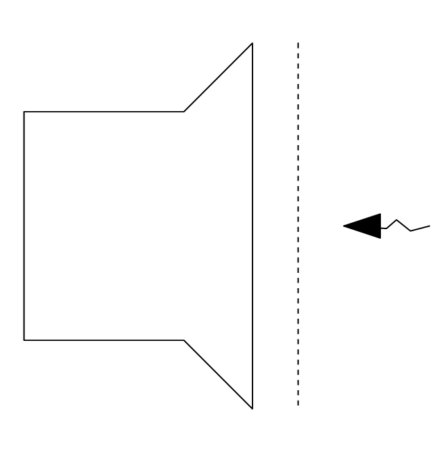
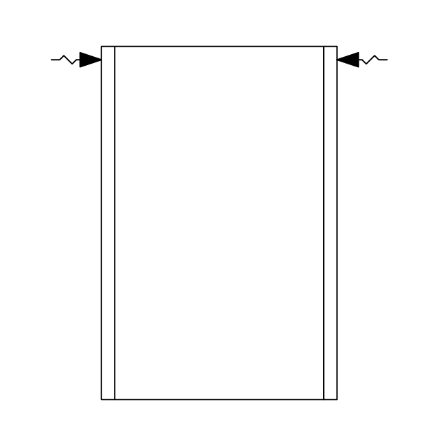
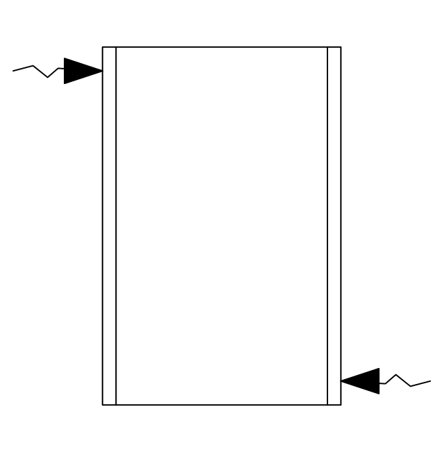
Rectangular inlet, flow arrow
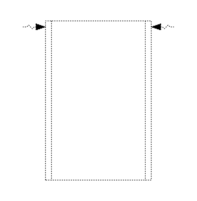
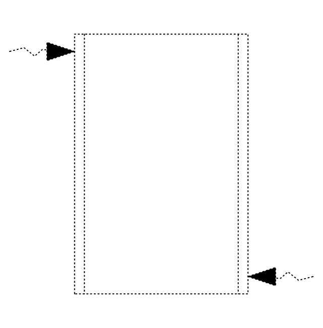
Rectangular inlet, flow arrow, hidden
Circular inlet
Circular inlet, hidden
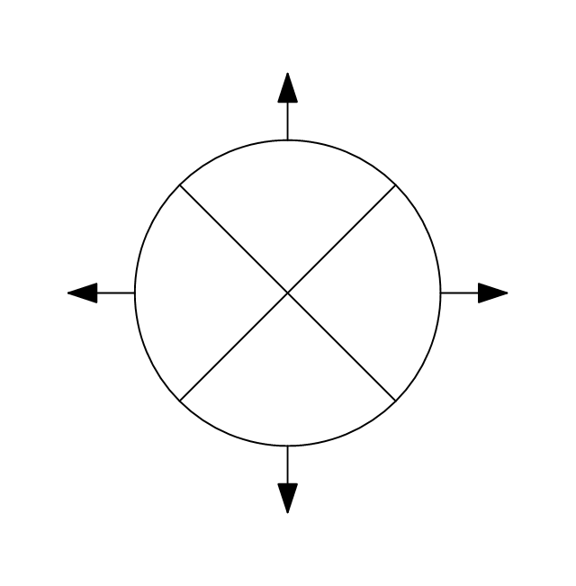
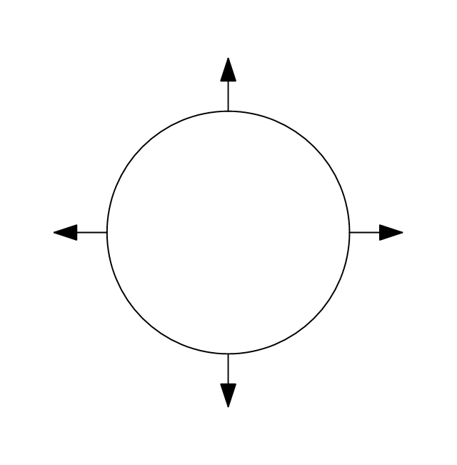
Circular inlet, flow arrow
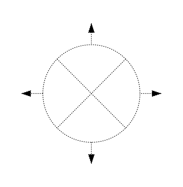
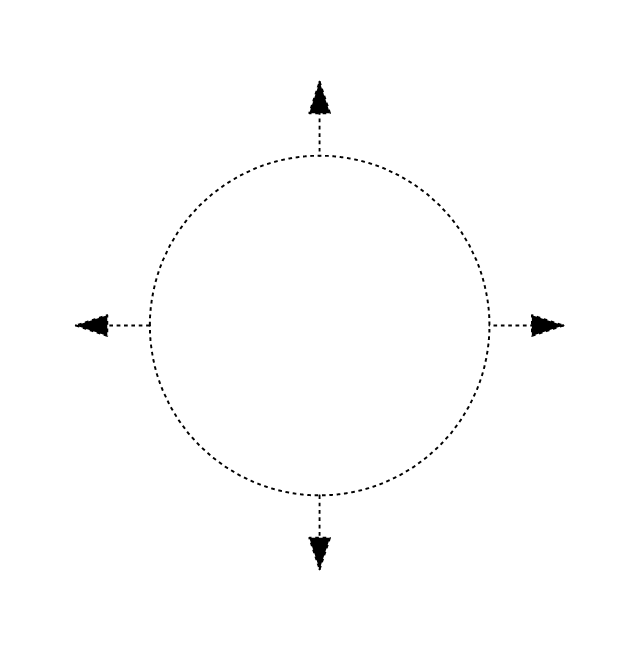
Circular inlet, flow arrow, hidden
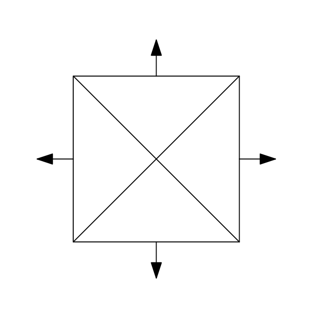
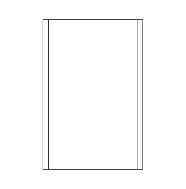
Rectangular outlet
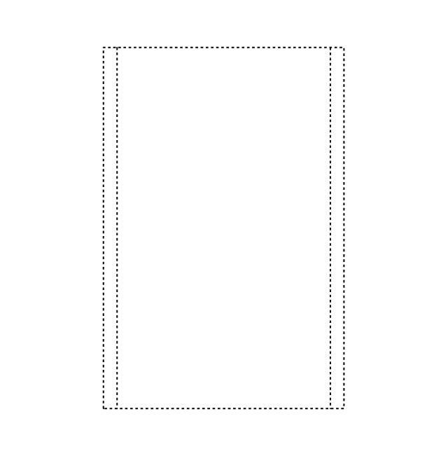
Rectangular outlet, hidden
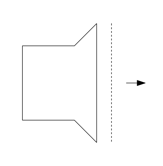
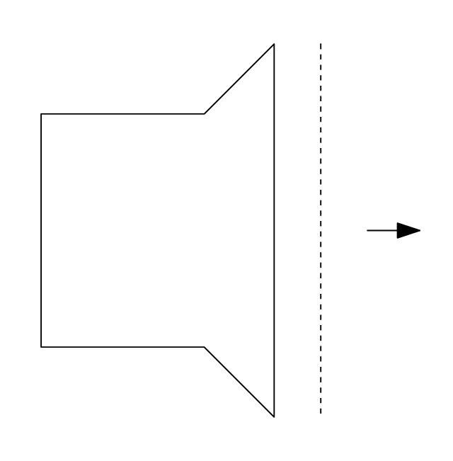
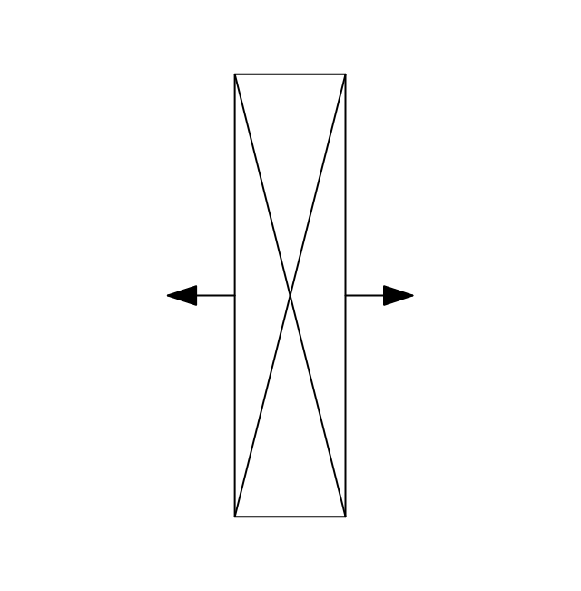
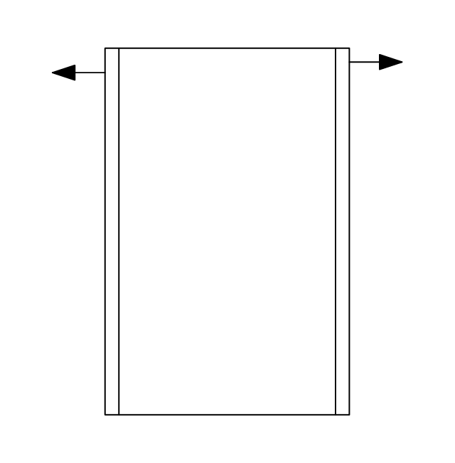
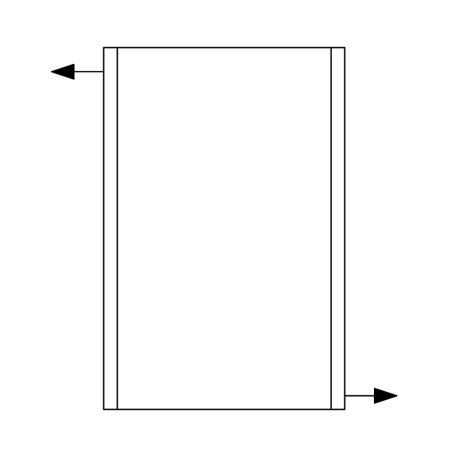
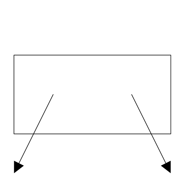
Rectangular outlet, flow arrows
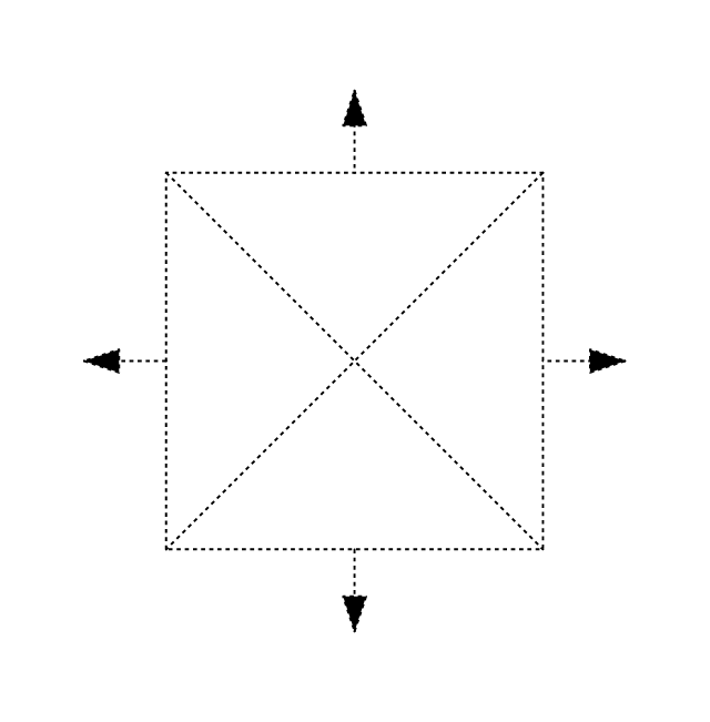
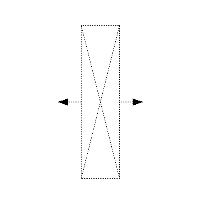
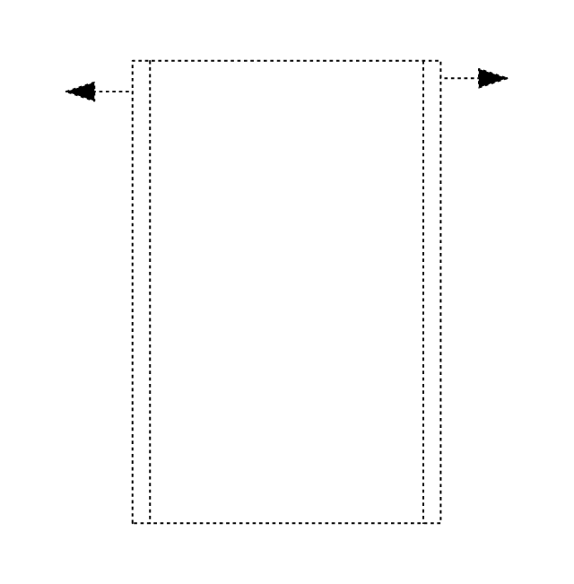
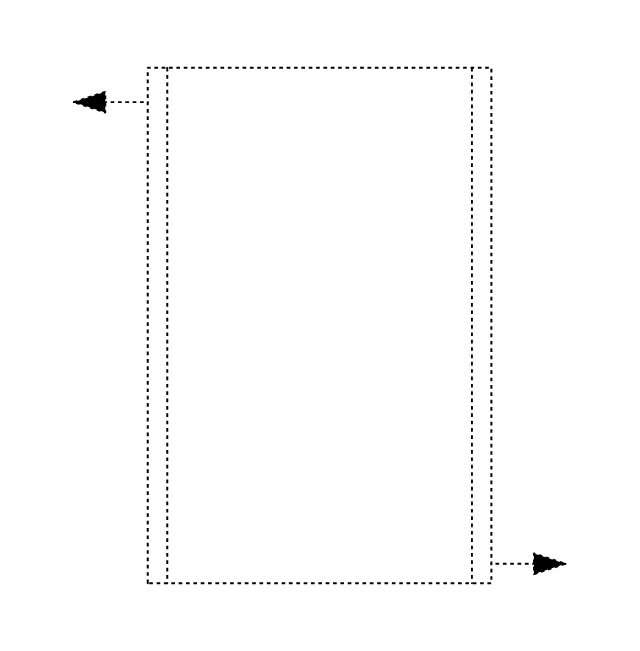
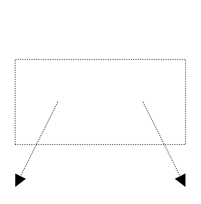
Rectangular outlet, flow arrows, hidden
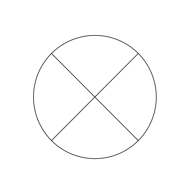
Circular outlet
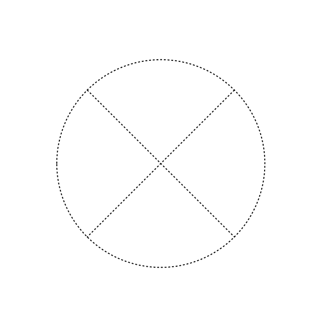
Circular outlet, hidden
Circular outlet, flow arrows
Circular outlet, flow arrows, hidden
Grille diffuser, rectangular duct
Grille diffuser, circular duct

Return grille diffuser, rectangular duct
Return grille diffuser, circular duct
Supply grille diffuser, rectangular duct
Supply grille diffuser, circular duct
Linear return diffuser
Linear return diffuser, hidden
Linear supply diffuser

Linear supply diffuser, hidden
Linear return diffuser, flow arrows
Linear return diffuser, flow arrows, hidden
Linear supply diffuser, flow arrows
Linear supply diffuser, flow arrows, hidden
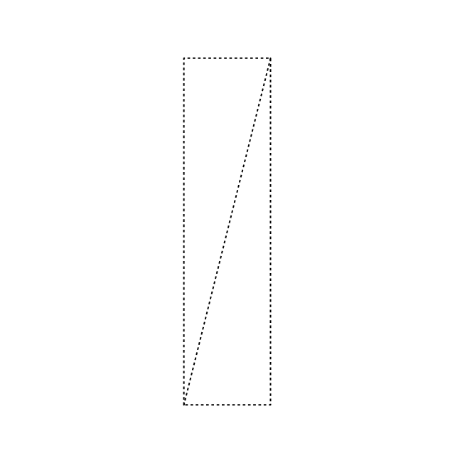
Troffer inlet / outlet
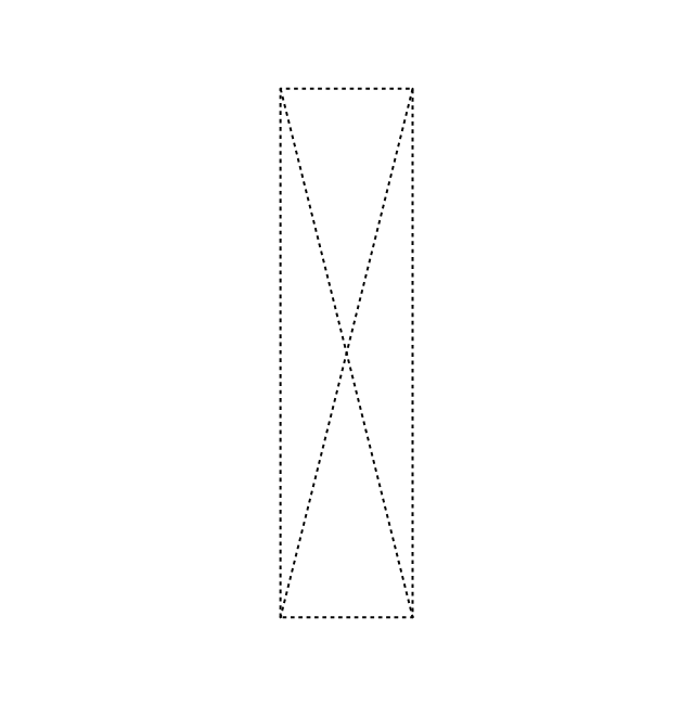
Troffer inlet / outlet, hidden
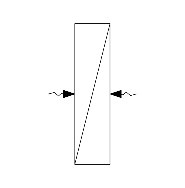
Troffer inlet, return diffuser
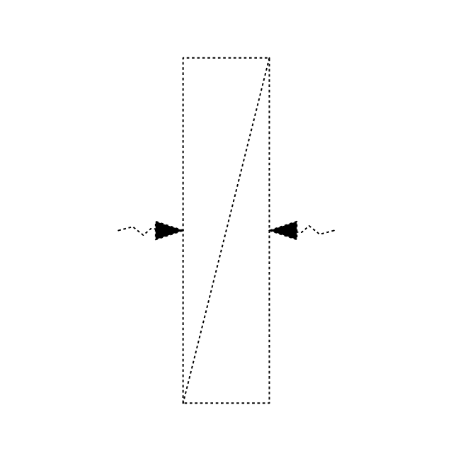
Troffer inlet, return diffuser, hidden
Troffer inlet, supply diffuser
Troffer inlet, supply diffuser, hidden
Troffer outlet, return diffuser
Troffer outlet, return diffuser, hidden
Troffer outlet, supply diffuser
Troffer outlet, supply diffuser, hidden
Circular outlet
Circular outlet, hidden
Grille
Grille, hidden
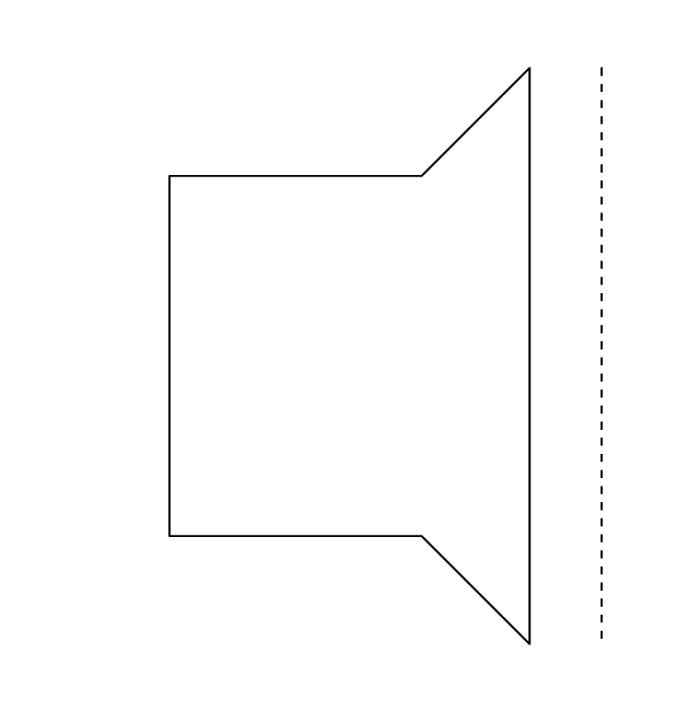
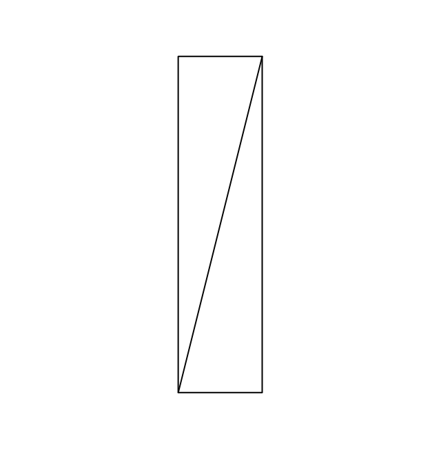
Grille (side)
-registers,-drills-and-diffusers---vector-stencils-library.png--diagram-flowchart-example.png)
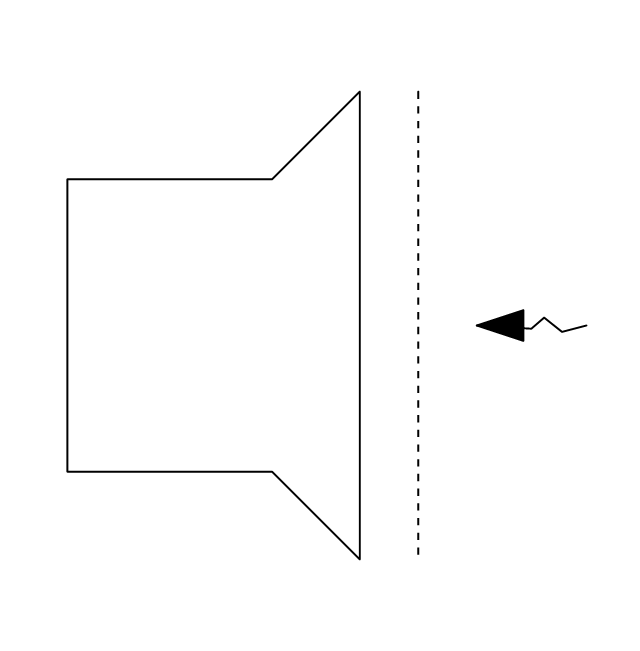
Grille (side), return diffuser
,-return-diffuser-registers,-drills-and-diffusers---vector-stencils-library.png--diagram-flowchart-example.png)
Grille (side), supply diffuser
,-supply-diffuser-registers,-drills-and-diffusers---vector-stencils-library.png--diagram-flowchart-example.png)
 Reflected Ceiling Plans
Reflected Ceiling Plans solution is effective tool for architects, designers, electricians, and other people which every day need convenient tool for representing their ceiling ideas. Use it to create without efforts professional Reflected Ceiling plans and Reflective Ceiling plans, showing the location of light fixtures, drywall or t-bar ceiling patterns, lighting panels, and HVAC grilles and diffusers that may be suspended from the ceiling.
- Reflected Ceiling Plans | Design elements - Registers, drills and ...
- Registers, drills and diffusers - Vector stencils library | Design ...
- Air Diffuser Symbol
- Building Plans Area | How to Create a Reflected Ceiling Floor Plan ...
- Inlet And Outlet Symbol
- Air Supply Air Return Ceiling Plan
- Hvac Supply Return Drawing Symbols
- Reflected Ceiling Plans | How to Create a Reflected Ceiling Floor ...
- Lighting and switch layout | Classroom lighting - Reflected ceiling ...