Basic Flowchart Symbols and Meaning


The vector stencils library "Map symbols" contains 10 spatial infographics symbols.
Use these signs and pictograms for drawing road and transit maps in the ConceptDraw PRO diagramming and vector drawing software extended with the Spatial Infographics solution from the area "What is Infographics" of ConceptDraw Solution Park.
Use these signs and pictograms for drawing road and transit maps in the ConceptDraw PRO diagramming and vector drawing software extended with the Spatial Infographics solution from the area "What is Infographics" of ConceptDraw Solution Park.
Windrose
North arrow
North arrow
Callout

Callout

Location

Direction Right

Direction Left

Direction Up

Direction Down

The vector stencils library "Dimensioning and tolerancing" contains 45 symbols of geometric dimensions and mechanical tolerances, geometric symbols, callouts, and text boxes and inserts.
Use these geometric dimensioning and tolerancing (GD&T) shapes to create annotated mechanical drawings in the ConceptDraw PRO diagramming and vector drawing software extended with the Mechanical Engineering solution from the Engineering area of ConceptDraw Solution Park.
www.conceptdraw.com/ solution-park/ engineering-mechanical
Datum (old)
-dimensioning-and-tolerancing---vector-stencils-library.png--diagram-flowchart-example.png)
Box callout

Datum symbol

Callout

All around callout

Text block

2 datum frame

Simple frame

Basic frame

1 datum frame

3 datum frame

Straightness

Flatness

Line profile

Circularity

Cylindricity

Surface profile

Position

Concentricity

Symmetry

Parallelism

Perpendicularity

Angularity

Material condition

Arc length

Diameter

Counterbore/ spotface

Countersink

Depth

Slope

Conical taper

Statistical tolerance

Datum (new)
-dimensioning-and-tolerancing---vector-stencils-library.png--diagram-flowchart-example.png)
Datum (new) 2
-2-dimensioning-and-tolerancing---vector-stencils-library.png--diagram-flowchart-example.png)
Target point

Target line

Target area (circle)
-dimensioning-and-tolerancing---vector-stencils-library.png--diagram-flowchart-example.png)
Target area (rectangle)
-dimensioning-and-tolerancing---vector-stencils-library.png--diagram-flowchart-example.png)
Total runout

Total runout 2

Circular runout

Circular runout 2

Surface finish

Surface finish, removal process

Surface finish, no process permitted

The vector stencils library "Dimensioning and tolerancing" contains 45 symbols of geometric dimensions and mechanical tolerances, geometric symbols, callouts, and text boxes and inserts.
Use these geometric dimensioning and tolerancing (GD&T) shapes to create annotated mechanical drawings in the ConceptDraw PRO diagramming and vector drawing software extended with the Mechanical Engineering solution from the Engineering area of ConceptDraw Solution Park.
www.conceptdraw.com/ solution-park/ engineering-mechanical
Use these geometric dimensioning and tolerancing (GD&T) shapes to create annotated mechanical drawings in the ConceptDraw PRO diagramming and vector drawing software extended with the Mechanical Engineering solution from the Engineering area of ConceptDraw Solution Park.
www.conceptdraw.com/ solution-park/ engineering-mechanical
Datum (old)
Box callout
Datum symbol
Callout
All around callout
Text block
2 datum frame
Simple frame
Basic frame
1 datum frame
3 datum frame
Straightness
Flatness
Line profile
Circularity
Cylindricity
Surface profile
Position
Concentricity
Symmetry
Parallelism
Perpendicularity
Angularity
Material condition
Arc length
Diameter
Counterbore/ spotface
Countersink
Depth
Slope
Conical taper
Statistical tolerance
Datum (new)
Datum (new) 2
Target point
Target line
Target area (circle)
Target area (rectangle)
Total runout
Total runout 2
Circular runout
Circular runout 2
Surface finish
Surface finish, removal process
Surface finish, no process permitted
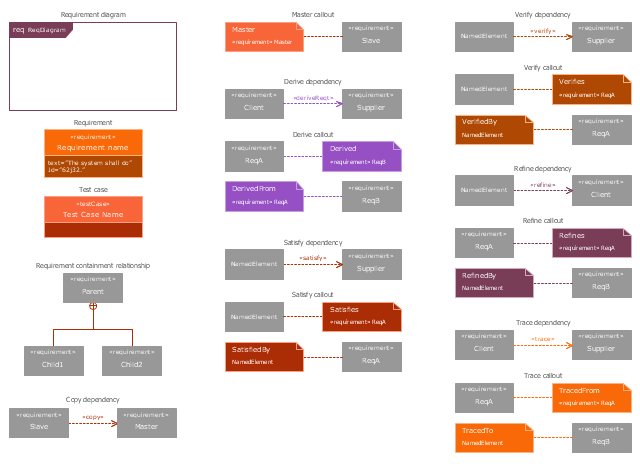
The vector stencils library "Requirement diagram" contains 21 SysML symbols.
Use it to design your requirement diagrams using ConceptDraw PRO diagramming and vector drawing software.
"A requirement specifies a capability or condition that must (or should) be satisfied. A requirement may specify a function that a system must perform or a performance condition a system must achieve. SysML provides modeling constructs to represent text-based requirements and relate them to other modeling elements. The requirements diagram described in this clause can depict the requirements in graphical, tabular, or tree structure format. A requirement can also appear on other diagrams to show its relationship to other modeling elements. The requirements modeling constructs are intended to provide a bridge between traditional requirements management tools and the other SysML models.
A requirement is defined as a stereotype of UML Class subject to a set of constraints. A standard requirement includes properties to specify its unique identifier and text requirement. Additional properties such as verification status, can be specified by the user.
Several requirements relationships are specified that enable the modeler to relate requirements to other requirements as well as to other model elements. These include relationships for defining a requirements hierarchy, deriving requirements, satisfying requirements, verifying requirements, and refining requirements." [www.omg.org/ spec/ SysML/ 1.3/ PDF]
The SysML shapes example "Design elements - Requirement diagram" is included in the SysML solution from the Software Development area of ConceptDraw Solution Park.
SysML requirement diagram symbols
The vector stencils library "Map symbols" contains 19 symbols for labeling the maps.
The pictograms example "Map symbols - Vector stencils library" was created using the ConceptDraw PRO diagramming and vector drawing software extended with the Directional Maps solution from the Maps area of ConceptDraw Solution Park.
The pictograms example "Map symbols - Vector stencils library" was created using the ConceptDraw PRO diagramming and vector drawing software extended with the Directional Maps solution from the Maps area of ConceptDraw Solution Park.
Compass

North

North arrow 1
North arrow 2
North arrow 3
North arrow 4
North arrow 5
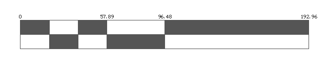
Scale
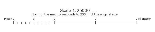
Scale symbol 1

Scale symbol 2
Horizontal

Vertical

Callout

Church

Cathedral

Viewpoint

Castle

Ruins

Curiosity

The vector stencils library "Map symbols" contains 10 spatial infographics symbols.
Use these signs and pictograms for drawing road and transit maps in the ConceptDraw PRO diagramming and vector drawing software extended with the Spatial Infographics solution from the area "What is Infographics" of ConceptDraw Solution Park.
Use these signs and pictograms for drawing road and transit maps in the ConceptDraw PRO diagramming and vector drawing software extended with the Spatial Infographics solution from the area "What is Infographics" of ConceptDraw Solution Park.
Windrose
North arrow
North arrow
Callout
Callout
Location
Direction Right
Direction Left
Direction Up
Direction Down
- Callout Web Design
- Profile Callout Symbol
- Basic Flowchart Symbols and Meaning | ERD Symbols and ...
- Run Out Symbol In Engineering Drawing
- Basic Flowchart Symbols and Meaning | ConceptDraw Arrows10 ...
- Design elements - Management titled callouts | Design elements ...
- Map symbols - Vector stencils library
- Paralisum Symbol
- Flat Design Callout Png