 Plant Layout Plans
This solution extends ConceptDraw PRO v.9.5 plant layout software (or later) with process plant layout and piping design samples, templates and libraries of vector stencils for drawing Plant Layout plans. Use it to develop plant layouts, power plant desig
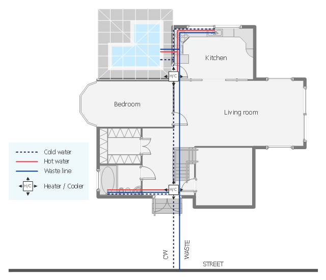
This plumbing and piping plan sample depicts the house hot and cold water supply and sanitation system.
"Within industry, piping is a system of pipes used to convey fluids (liquids and gases) from one location to another. The engineering discipline of piping design studies the efficient transport of fluid. ...
Plumbing is a piping system with which most people are familiar, as it constitutes the form of fluid transportation that is used to provide potable water and fuels to their homes and businesses. Plumbing pipes also remove waste in the form of sewage, and allow venting of sewage gases to the outdoors. Fire sprinkler systems also use piping, and may transport nonpotable or potable water, or other fire-suppression fluids." [Piping. Wikipedia]
The water supply and waste removal system scheme example "House plumbing plan" was created using the ConceptDraw PRO diagramming and vector drawing software extended with the Plumbing and Piping Plans solution from the Building Plans area of ConceptDraw Solution Park.
Plumbing and piping plan
HelpDesk
How to Draw a Chemical Process Flow Diagram

- Diagram Of Industry Building Plan
- How To Draw Building Plans | Plant Layout Plans | Warehouse with ...
- Industry Building Plan
- Industry Plan Layout
- A Plan Sketch Of Software Industry Building
- Fitness Industry Business Plan
- Plant Layout Plans | How to Draw a Building Plans | How To use ...
- Process Flowchart | Chemical and Process Engineering | Building ...
- Plant Layout Plans | Factory layout floor plan | Emergency Plan ...
- Industry Floor Plan
- Diagram Of An Electrical Drawing Of An Industry
- Process Flowchart | Building Drawing Design Element: Piping Plan ...
- How To use House Electrical Plan Software | Electrical Drawing ...
- Symbols Used In Layout Making Of Industry
- Ground Floor Plan For Industry
- Plant Layout Plans | CAD Drawing Software for Making Mechanic ...
- Building Drawing Design Element: Piping Plan | Plumbing and ...
- Factory layout floor plan | Plant Layout Plans | Bar Diagrams for ...
- Drawing Symbols Used In The Building Industry
- Electrical Drawing Software | How To use House Electrical Plan ...