 ATM UML Diagrams
The ATM UML Diagrams solution lets you create ATM solutions and UML examples. Use ConceptDraw DIAGRAM as a UML diagram creator to visualize a banking system.
UML Collaboration Diagram. Design Elements

Bank UML Diagram

Software Diagram Examples and Templates

UML Use Case Diagram. Design Elements


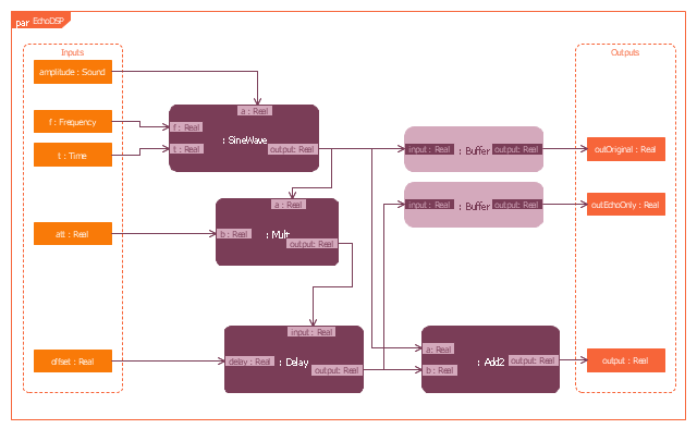
UML Deployment Diagram Example - ATM System UML diagrams

UML Software

This example was created on the base of SysML parametric diagram of MP3 playe on page 11 of "SysML Modelling Language explained" document from the OMG Systems Modeling Language website.
[omgsysml.org/ SysML_ Modelling_ Language_ explained-finance.pdf]
"A parametric diagram is defined as a restricted form of internal block diagram. A parametric diagram may contain
constraint properties and their parameters, along with other properties from within the internal block context. All
properties that appear, other than the constraints themselves, must either be bound directly to a constraint parameter, or contain a property that is bound to one (through any number of levels of containment)." [omg.org/ spec/ SysML/ 1.3/ PDF]
The example "Parametric diagram" was drawn using the ConceptDraw PRO diagramming and vector drawing software extended with the SysML solution from the Software Development area of ConceptDraw Solution Park.
SysML parametric diagram
Entity Relationship Diagram Software Engineering

- Block Diagram Of Atm Machine
- ATM UML Diagrams | Block Diagrams | Bank UML Diagram ...
- Circular Arrows Diagrams | Block Diagrams | Rapid UML | Sdlc ...
- Atm Block And Architecture Diagrams
- ATM UML Diagrams | ConceptDraw Solution Park | Accounting ...
- ATM UML Diagrams | Entity-Relationship Diagram (ERD) | Block ...
- Block Diagram Of Atm Machine Pdf Format
- Block Diagram Atm Machine
- Block Diagrams | ATM UML Diagrams | Interactive Voice Response ...
- Business Process Model and Notation | Block Diagrams | ATM UML ...