UML Deployment Diagram Example - ATM System UML diagrams

UML Deployment Diagram

UML Deployment Diagram. Design Elements

Bank Sequence Diagram

UML Use Case Diagram Example. Services UML Diagram. ATM system

UML Activity Diagram

UML Collaboration Diagram. Design Elements

HelpDesk
How to Create a Bank ATM Use Case Diagram

Banking System

ATM Solutions
UML Diagram

Bank UML Diagram

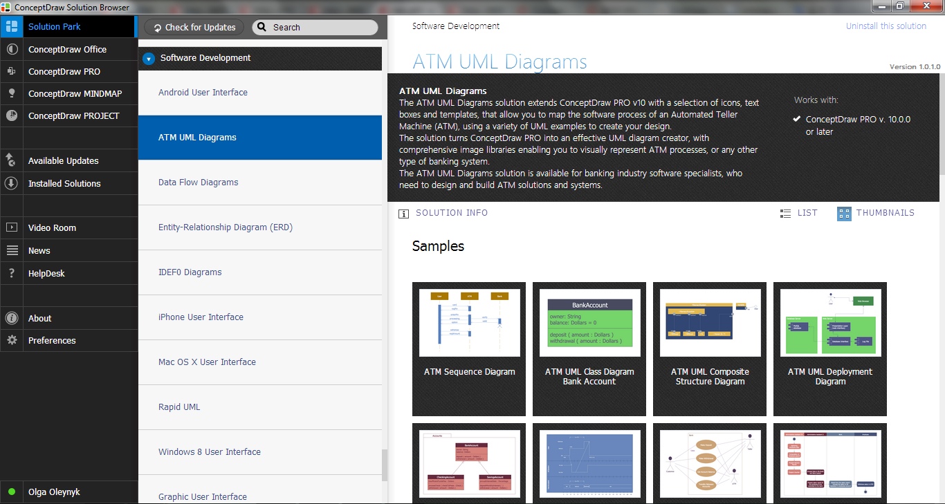
 ATM UML Diagrams
The ATM UML Diagrams solution lets you create ATM solutions and UML examples. Use ConceptDraw DIAGRAM as a UML diagram creator to visualize a banking system.
The vector stencils library "Bank UML deployment diagram" contains 10 shapes for drawing UML deployment diagrams.
Use it for object-oriented modeling of your bank information system.
"A deployment diagram in the Unified Modeling Language models the physical deployment of artifacts on nodes. To describe a web site, for example, a deployment diagram would show what hardware components ("nodes") exist (e.g., a web server, an application server, and a database server), what software components ("artifacts") run on each node (e.g., web application, database), and how the different pieces are connected (e.g. JDBC, REST, RMI).
The nodes appear as boxes, and the artifacts allocated to each node appear as rectangles within the boxes. Nodes may have subnodes, which appear as nested boxes. A single node in a deployment diagram may conceptually represent multiple physical nodes, such as a cluster of database servers.
There are two types of Nodes:
1. Device Node.
2. Execution Environment Node.
Device nodes are physical computing resources with processing memory and services to execute software, such as typical computers or mobile phones. An execution environment node (EEN) is a software computing resource that runs within an outer node and which itself provides a service to host and execute other executable software elements." [Deployment diagram. Wikipedia]
This example of UML deployment diagram symbols for the ConceptDraw PRO diagramming and vector drawing software is included in the ATM UML Diagrams solution from the Software Development area of ConceptDraw Solution Park.
UML deployment diagram symbols

 AWS Architecture Diagrams
AWS Architecture Diagrams with powerful drawing tools and numerous predesigned Amazon icons and AWS simple icons is the best for creation the AWS Architecture Diagrams, describing the use of Amazon Web Services or Amazon Cloud Services, their application for development and implementation the systems running on the AWS infrastructure. The multifarious samples give you the good understanding of AWS platform, its structure, services, resources and features, wide opportunities, advantages and benefits from their use; solution’s templates are essential and helpful when designing, description and implementing the AWS infrastructure-based systems. Use them in technical documentation, advertising and marketing materials, in specifications, presentation slides, whitepapers, datasheets, posters, etc.
- UML Deployment Diagram Example - ATM System UML diagrams ...
- UML Deployment Diagram Example
- UML Deployment Diagram Example - ATM System UML diagrams ...
- ATM UML Diagrams | UML Deployment Diagram Example - ATM ...
- UML Use Case Diagram Example. Services UML Diagram . ATM ...
- UML Deployment Diagram Example - ATM System UML diagrams ...
- UML Deployment Diagram Example - ATM System UML diagrams
- Atm Systems Deployment Diagram In Uml
- How To Draw Deployment Diagram
- UML Deployment Diagram Example - ATM System UML diagrams ...
- Bank Sequence Diagram | UML Deployment Diagram Example ...
- UML Activity Diagram | UML Deployment Diagram Example - ATM ...
- UML Diagram
- Bank Sequence Diagram | ATM UML Diagrams | UML Deployment ...
- Bank ATM use case diagram | UML Deployment Diagram Example ...
- Bank Sequence Diagram | Bank System | UML Deployment Diagram ...
- UML Deployment Diagram Example - ATM System UML diagrams ...
- UML Package Diagram . Design Elements | UML Deployment ...
- UML Diagram Types List | UML Deployment Diagram Example ...
- UML Activity Diagram | UML Deployment Diagram Example - ATM ...