 ATM UML Diagrams
The ATM UML Diagrams solution lets you create ATM solutions and UML examples. Use ConceptDraw DIAGRAM as a UML diagram creator to visualize a banking system.
UML Use Case Diagram Example. Services UML Diagram. ATM system

Bank UML Diagram

Bank System
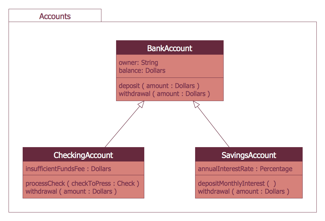
UML Diagram

State Machine Diagram


UML Tool & UML Diagram Examples

UML Deployment Diagram Example - ATM System UML diagrams

UML Diagram
Sequence UML for ATM
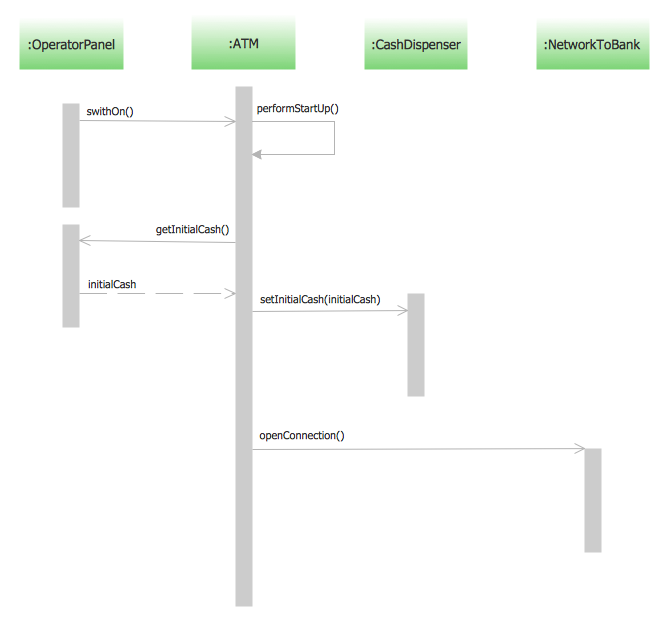
- ATM Sequence diagram | UML activity diagram - Cash withdrawal ...
- UML activity diagram - Cash withdrawal from ATM | ATM UML ...
- Uml Atm
- UML activity diagram - Cash withdrawal from ATM | Bank ATM use ...
- UML activity diagram - Cash withdrawal from ATM | UML ...
- UML activity diagram - Cash withdrawal from ATM | ATM UML ...
- UML activity diagram - Cash withdrawal from ATM | UML ...
- Complete Use Case Diagram For Atm Withdrawal
- How to Create a Bank ATM Use Case Diagram | ATM UML ...
- Design elements - Bank UML activity diagram | UML activity diagram ...