Electrical Symbols, Electrical Diagram Symbols

Electrical Design Software

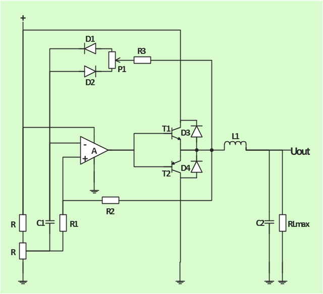
The analogue electronics diagram "Simple switched supply" was redesigned from the Wikimedia Commons file: Switchat.png.
[commons.wikimedia.org/ wiki/ File:Switchat.png]
"Analogue electronics (or analog in American English) are electronic systems with a continuously variable signal, in contrast to digital electronics where signals usually take only two different levels. The term "analogue" describes the proportional relationship between a signal and a voltage or current that represents the signal." [Analogue electronics. Wikipedia]
The circuit diagram example "Simple switched supply" was created using the ConceptDraw PRO diagramming and vector drawing software extended with the Electrical Engineering solution from the Engineering area of ConceptDraw Solution Park.
Circuit diagram
How To use Electrical and Telecom Plan Software


Wiring Diagrams with ConceptDraw DIAGRAM

The circuit diagram example "Amplifier" was redesigned from the Wikimedia Commons file: Slika br.5.JPG.
[commons.wikimedia.org/ wiki/ File:Slika_ br.5.JPG]
This file is made available under the Creative Commons CC0 1.0 Universal Public Domain Dedication. [creativecommons.org/ publicdomain/ zero/ 1.0/ deed.en]
"An electronic amplifier, amplifier, or (informally) amp is an electronic device that increases the power of a signal. It does this by taking energy from a power supply and controlling the output to match the input signal shape but with a larger amplitude. In this sense, an amplifier modulates the output of the power supply.
There are four basic types of electronic amplifier: the voltage amplifier, the current amplifier, the transconductance amplifier, and the transresistance amplifier. A further distinction is whether the output is a linear or nonlinear representation of the input. Amplifiers can also be categorized by their physical placement in the signal chain." [Amplifier. Wikipedia]
The circuit diagram example "Amplifier" was created using the ConceptDraw PRO diagramming and vector drawing software extended with the Electrical Engineering solution from the Engineering area of ConceptDraw Solution Park.
Circuit diagram
Electrical Symbols — VHF UHF SHF

"In electronics, a vacuum tube, electron tube (in North America), tube, or thermionic valve or valve (in British English) is a device controlling electric current through a vacuum in a sealed container. The simplest vacuum tube, the diode, contains only two elements; current can only flow in one direction through the device between the two electrodes, as electrons emitted by the hot cathode travel through the tube and are collected by the anode. Addition of a third and additional electrodes allows the current flowing between cathode and anode to be controlled in various ways. The device can be used as an electronic amplifier, a rectifier, an electronically controlled switch, an oscillator, and for other purposes.
Vacuum tubes mostly rely on thermionic emission of electrons from a hot filament or a cathode heated by the filament. Some electron tube devices rely on the properties of a discharge through an ionized gas." [Vacuum tube. Wikipedia]
"The EL34 is a thermionic valve or vacuum tube of the power pentode type. It has an international octal base (indicated by the '3' in the part number) and is found mainly in the final output stages of audio amplification circuits and was designed to be suitable as a series regulator by virtue of its high permissible voltage between heater and cathode and other parameters. The American RETMA tube designation number for this tube is 6CA7. Russian analog is 6P27S (Cyrillic: 6П27C )" [EL34. Wikipedia]
This circuit diagram sample was redrawn from the Wikipedia Commons file: EL34 schematics (circuit diagram).gif. [commons.wikimedia.org/ wiki/ File:EL34_ schematics_ %28circuit_ diagram%29.gif]
The example "Circuit diagram - EL 34 schematics" was drawn using the ConceptDraw PRO diagramming and vector drawing software extended with the Electrical Engineering solution from the Engineering area of ConceptDraw Solution Park.
EL34 shemathics

Cisco Network Design. Cisco icons, shapes, stencils, symbols and design elements

- Circuit diagram
- Amplifier - Circuit diagram | Composite assemblies - Vector stencils ...
- Amplifier - Circuit diagram | Bipolar current mirror - Circuit diagram ...
- Electrical Drawing Software and Electrical Symbols | Circuits and ...
- Amplifier - Circuit diagram | Design elements - Transistors | Simple ...
- Simple switched supply - Circuit diagram | Electrical Drawing ...
- Simple switched supply - Circuit diagram | Electrical Diagram ...
- Example Of Circuit Symbol For Fixed Resistor
- Amplifier Circuit Schematics
- Bipolar current mirror - Circuit diagram | Amplifier - Circuit diagram ...
- Electrical Diagram Software | Bipolar current mirror - Circuit diagram ...
- Design elements - Electrical circuits | Amplifier - Circuit diagram ...
- Give Me Circuit Diagram Of Regulators Fixed And Adjustable Ones
- Simple switched supply - Circuit diagram | Circuit diagram - EL 34 ...
- Power Engineering Schematic Diagram
- Electrical circuits - Vector stencils library | How To use House ...
- Electrical Symbols, Electrical Diagram Symbols | Electrical ...
- Design elements - Electrical circuits
- Electrical Symbols — Power Sources | Electrical Symbols, Electrical ...
- Electrical Symbols, Electrical Schematic Symbols | Electrical ...