Made with
ConceptDraw
DIAGRAM 18

UML Object Diagram

How To Draw UML Object Diagrams

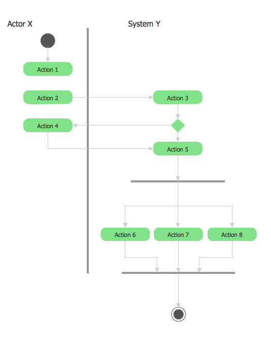
UML Object Diagram shows the structure of a modelled system at a specific time. UML Object Diagram focuses on some particular set of object instances and attributes, and the links between the instances. A correlated set of object diagrams provides insight into how an arbitrary view of a system is expected to evolve over time. ConceptDraw has four examples that help you to start using software for drawing UML Object Diagrams. You can use the appropriate stencils of UML notation for drawing own UML Object Diagram.

UML Object Diagram *

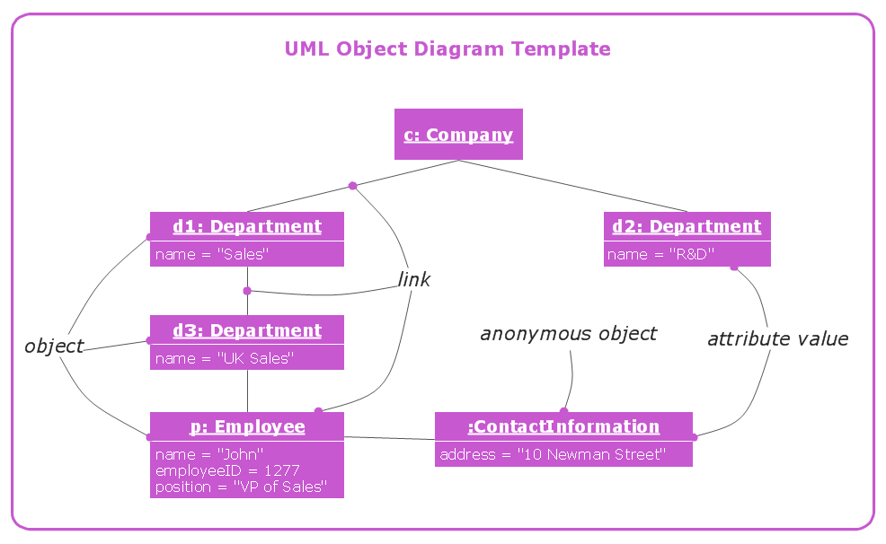
This UML object diagram template is created using ConceptDraw DIAGRAM diagramming and vector drawing software enhanced with Rapid UML solution from ConceptDraw Solution Park.

Rapid UML solution provides templates, examples and libraries of stencils for quick and easy drawing the all types of system and software engineering diagrams according to UML 2.4 notation.

Use ConceptDraw DIAGRAM with UML object diagram templates, samples and stencil library from Rapid UML solution to show the particular set of system objects, their attributes and the links between them.

THREE RELATED HOW TO's:
The Rapid UML solution provides diagram examples, templates and vector stencils libraries for quick and easy drawing all types of UML 2.x and 1.x diagramsUML Business Process
Picture: UML Business Process
Related Solution:
When we start to speak about databases, we must always mention database structure visualization. One of the most common ways to do it is to create an entity relationship diagram, and to put appropriate symbols on it. It is important either for database projecting and for its' future maintenance. Entity Relationship Diagram describes data elements and their relationships within a database. There are a set of special symbols that depict each element of an entity relationship diagram. Entities - represents some stable components such as supplier, employee, invoice, client, etc. Relation symbols show how the entities interact. Attributes define characteristics of the relationships. Attributes can be one-to-one or many-to-many. Physical symbols is used in the physical models. They represent items such as fields, tables, types and keys. ERD physical symbols are the building material for the database. Notation lines are used to illustrate the relationships. The most common method is Crow’s Feet notation. You can use ConceptDraw Entity-Relationship Diagram (ERD) solution to represent a database using the Entity-Relationship model.Entity Relationship Diagram Symbols
Picture: Entity Relationship Diagram Symbols
Related Solution:
This sample was created in ConceptDraw DIAGRAM diagramming and vector drawing software using the UML Activity Diagram library of the Rapid UML Solution from the Software Development area of ConceptDraw Solution Park.UML 2 4 Process Flow Diagram *
Picture: UML 2 4 Process Flow Diagram
Related Solution:
ConceptDraw
DIAGRAM 18