ORM
Object-role modeling (ORM) is what can be used for modeling the needed semantics of the needed universe of discourse. Object-role modeling (ORM) is known to be often used either for software engineering and/or for data modeling. Any object-role model is known to be using different graphical symbols that can be based on the so-called “first order predicate logic” as well as a “set theory”. The object-role models are expected to enable the modeler to create some unambiguous definition. Such definition should be made of an arbitrary universe of discourse.
Being attribute free, the predicates of any ORM model that can be considered lend themselves to the design of the graph database models as well as the analysis in an ORM that was known to be originally conceived for benefiting the relational database designs.
An object-role model is a term that was coined in the 1970s. The so-called “ORM based tools” are since widely used (for over 30 years now) as they are convenient for such processes as data modeling. Object-role modeling has recently been used for modeling the XML-Schemas, business rules, data warehouses, web forms and requirements engineering.
Such models as the object-role ones are known to be based on the elementary facts. They expressed in diagrams that can be later verbalized into a natural language. Any fact is simply a proposition and with ORM such propositions are abstracted into the so-called "fact types". At the same time, the individual propositions are regarded as a sample data.
There is a difference between two terms — a "fact" and an "elementary fact". It is that no elementary fact can be simplified with no loss of meaning. Such "fact-based" approach is what can facilitate transforming, querying and modeling the needed information from any needed domain.
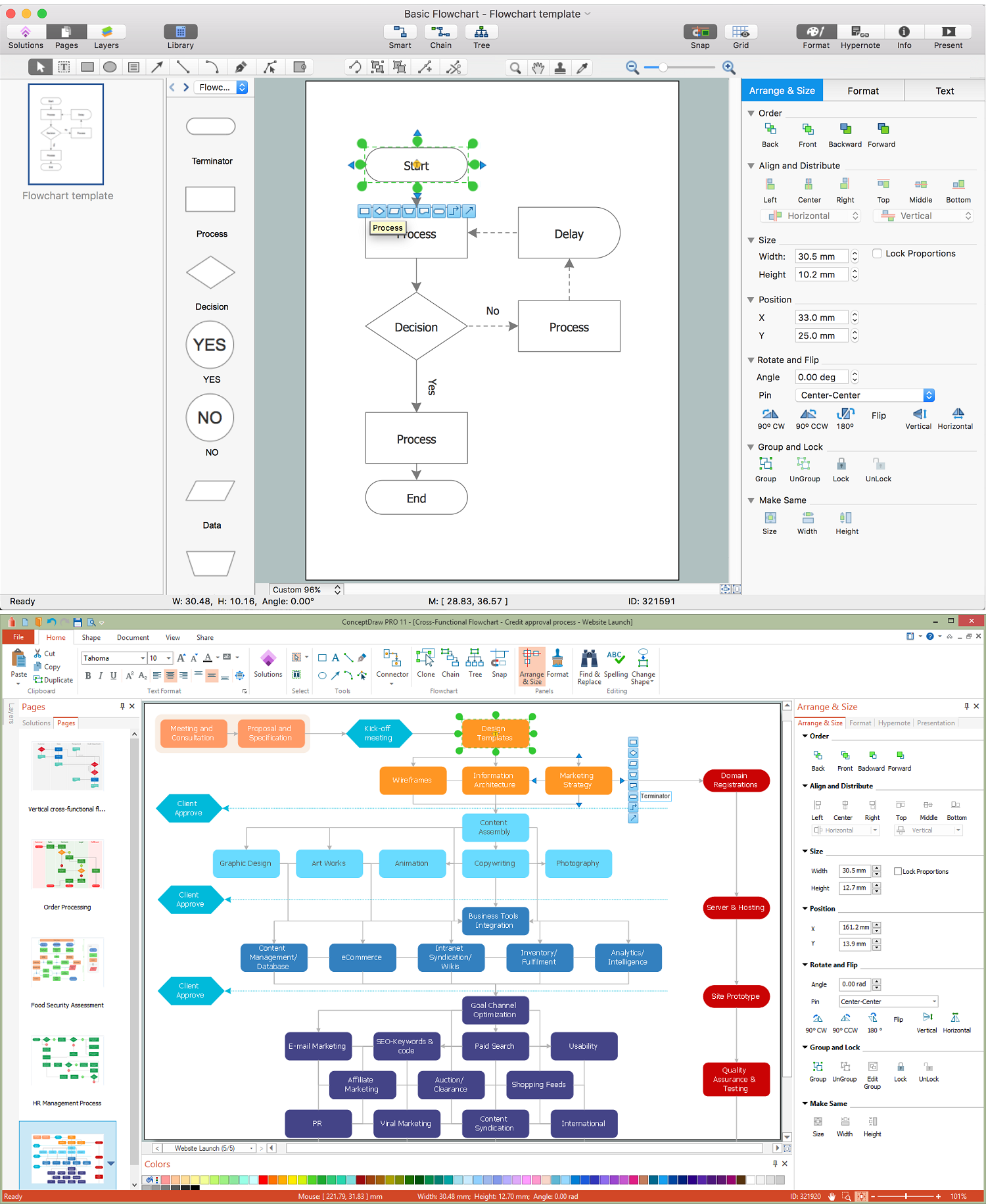
Example 1. Object-Role Modeling ORM Diagram
ORM is what it is known to be an “attribute-free” meaning that it treats all the elementary facts as relationships. It means that it treats the decisions for grouping the facts into structures such as the attribute-based entity types, relation and XML schemas and classes do. An implementation is known to be concerning irrelevant to semantics. Any object-role modeling is what improves the semantic stability, enabling verbalization into a natural language.
Fact-based modeling is known to be including different procedures that can be used for mapping the facts to the so-called “attribute-based structures”. An example of such structure can be the one of UML or ER.
The fact-based textual representations are all based on the formal subsets of native languages and many ORM proponents argue that its models are much simpler to understand by people who do not have enough technical education to understand the other ones.
Thus, some people argue that object-role models are simpler to understand than any declarative language as well as other graphical ones. All the fact-based graphical notations are usually more expressive than the ER or UML ones. The object-role models can be automatically mapped to both deductive and relational databases.
Knowing ORM2 as the latest generation of the object-role modeling, its main objectives for the ORM 2 graphical notation include it having a more compact display of ORM models having no compromises on the clarity. It also has an improved internationalization, being simplified on drawing the rules in order to facilitate the creation of any graphical editor. Having the extended use of views for selectively suppressing/displaying details, the ORM 2 graphical notation also supports the new features such as the role path delineation, the modalities and the closure aspects.
Any system development usually involves a few stages such as feasibility study, conceptual design of data and operations, requirements analysis, logical design, external design, internal design and implementation, prototyping, testing, validation and maintenance. There are all together seven steps of any conceptual schema design procedure that involve transforming all the familiar information examples into elementary facts, applying the so-called “quality checks”, drawing the fact types, checking for entity types that should be combined, noting any arithmetic derivations and adding uniqueness constraints, mandatory role constraints, value, set comparison and subtyping constraints as well as other constraints. The mentioned seven steps also include performing the final checks and checking the so-called “logical derivations” as well as the arity of the fact types.
Object-role modeling's conceptual schema design procedure is known to be focusing on the analysis as well as the design of data. All the roots of any object-role modeling can be traced for a research into semantic modeling for information systems as it evolved from the so-called “Natural language Information Analysis Method”. The mentioned method is a methodology that was initially developed by G.M. Nijssen in the mid-1970s in the Netherlands.
There was another recent development which is the use of an object-role modeling in combination with the standardized relation types which have the associated roles as well as a standard machine-readable dictionary. It also has a taxonomy of concepts that are also provided in the Gellish English dictionary. Such standardization of the relation types, concepts and roles is what enables the increased possibilities for any model reuse and model integration.

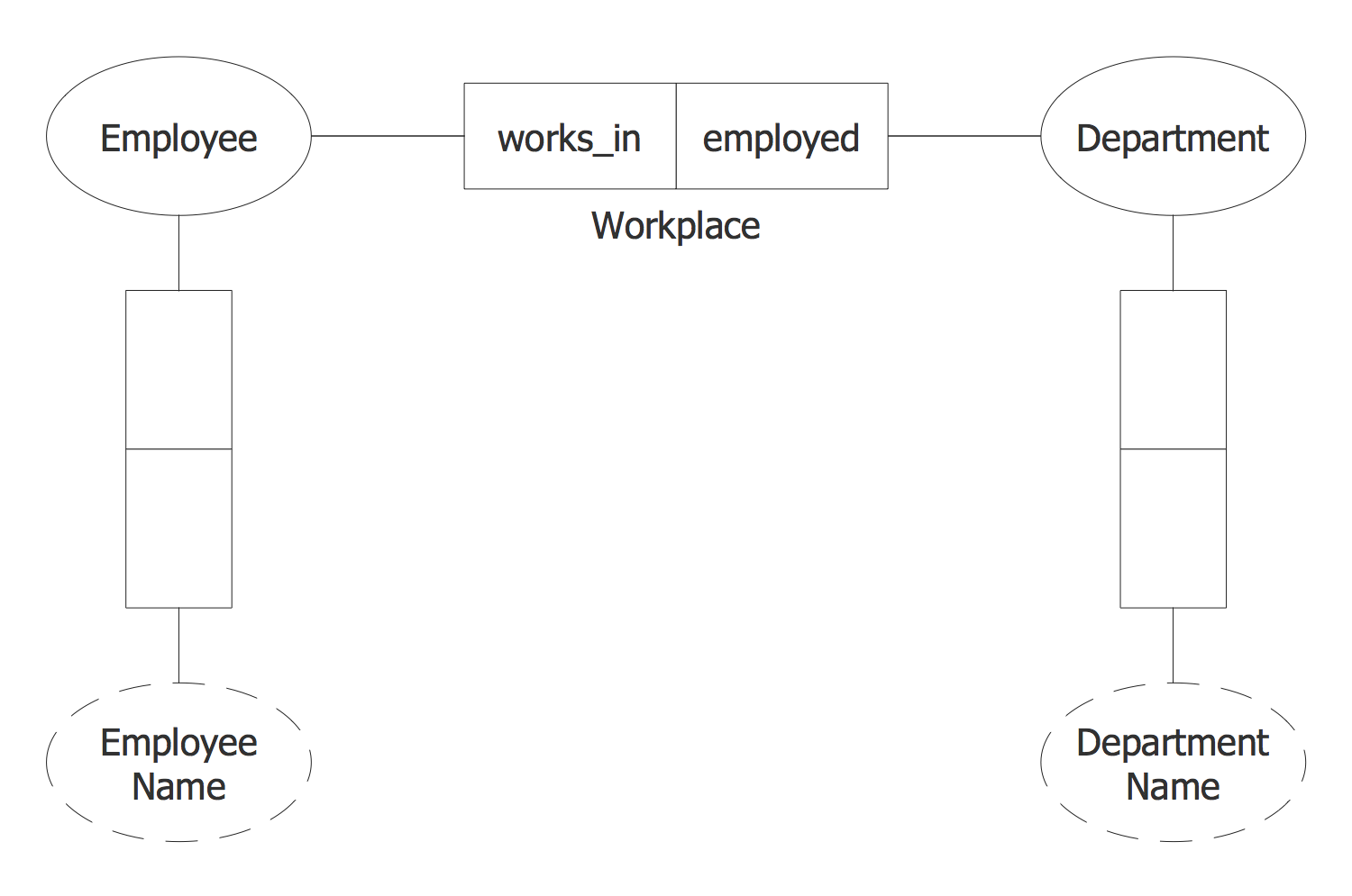
Example 2. Object-Role Modeling ORM Diagram solution
There is more information about ORM in the other articles on this site and in case some ORM drawing has to be created, such as an ORM diagram, it can become possible once the ConceptDraw DIAGRAM diagramming and drawing software is downloaded from this site being used with another product of CS — the ConceptDraw STORE. Having the last-mentioned application, you can choose to install the Object-Role Modeling (ORM) solution in order to make any needed ORM diagram by using the pre-made templates of such drawings as well as the vector stencil libraries from the mentioned solution.