EPC IT Solutions
EPC IT Solutions are very popular now for drawing various EPC diagrams which are widely used for modeling and analyzing the business processes. ConceptDraw DIAGRAM software is not exception and provides the powerful Event-driven Process Chain Diagrams EPC solution from the Business Processes Area.
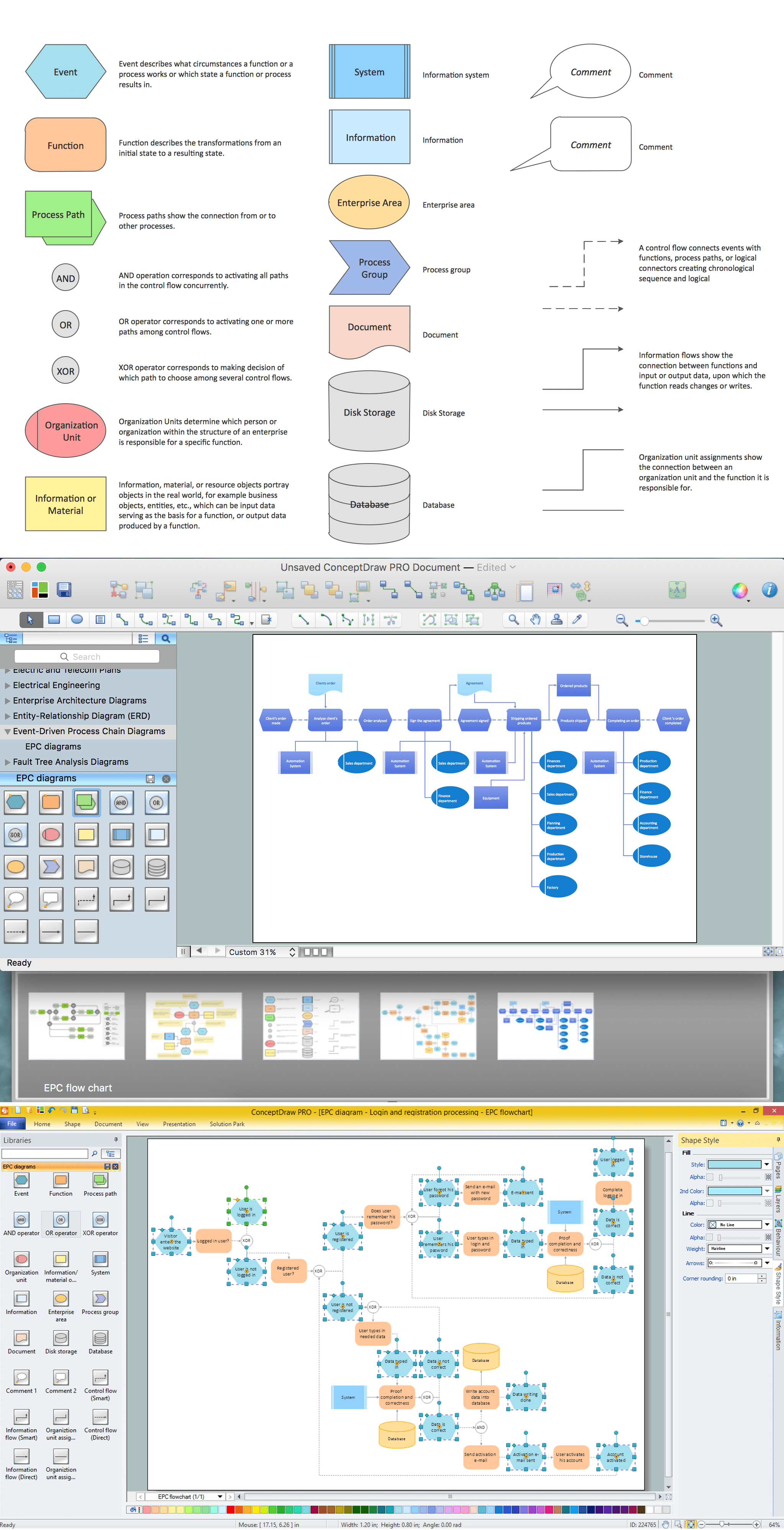
EPC is an ordered graph of events and functions that allows alternative and parallel execution of processes owing to use of connectors and logical operators OR, AND, XOR.
Example 1. EPC IT Solutions - ConceptDraw DIAGRAM /p>
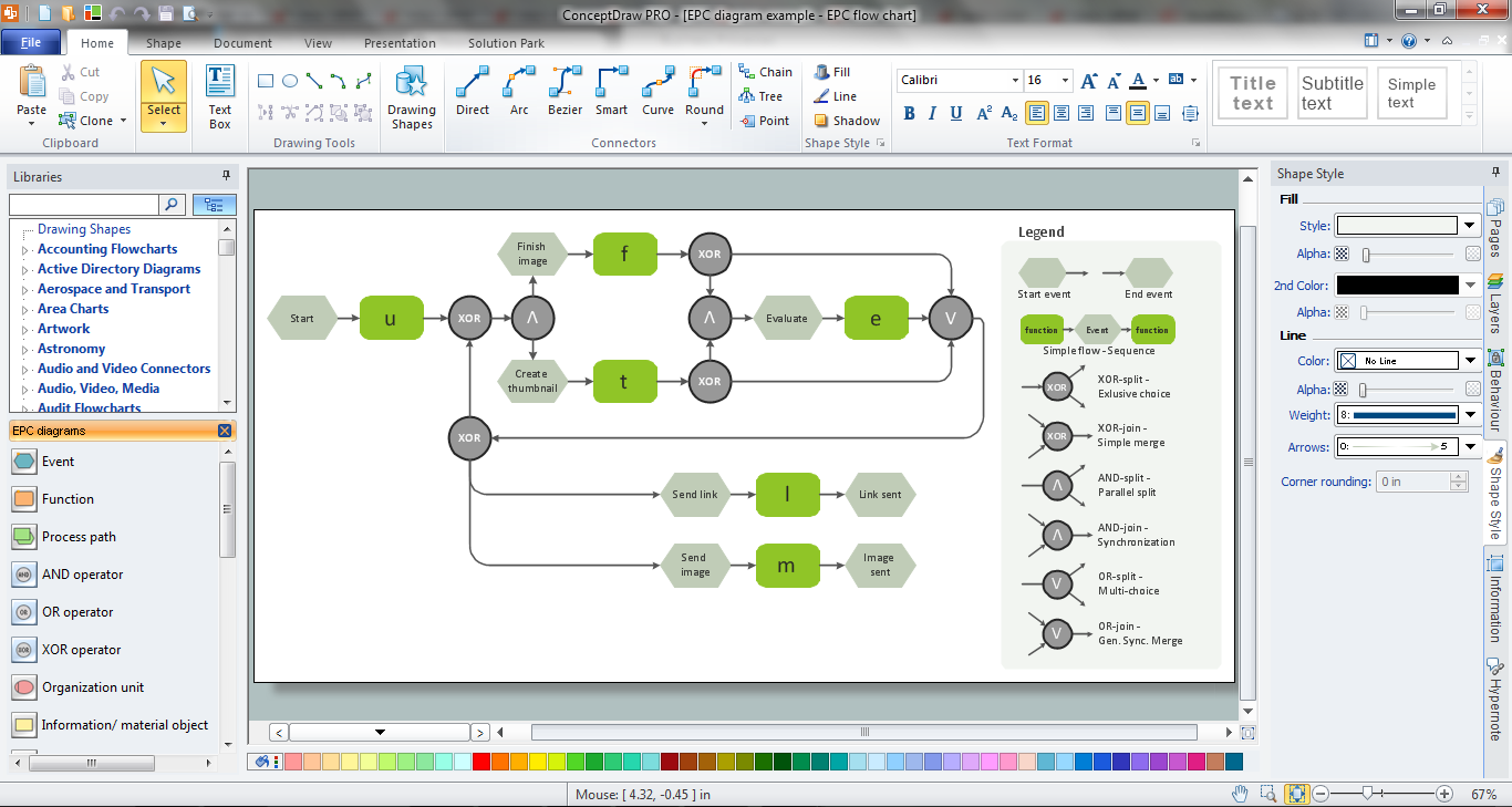
Event-driven Process Chain Diagrams EPC Solution provides a variety of ready-to-use vector shapes grouped in EPC Diagrams library. They are useful for quickly creating the EPC diagram and not require the professional artistic abilities.

Example 2. Event-driven Process Chain Diagrams EPC Solution in ConceptDraw STORE
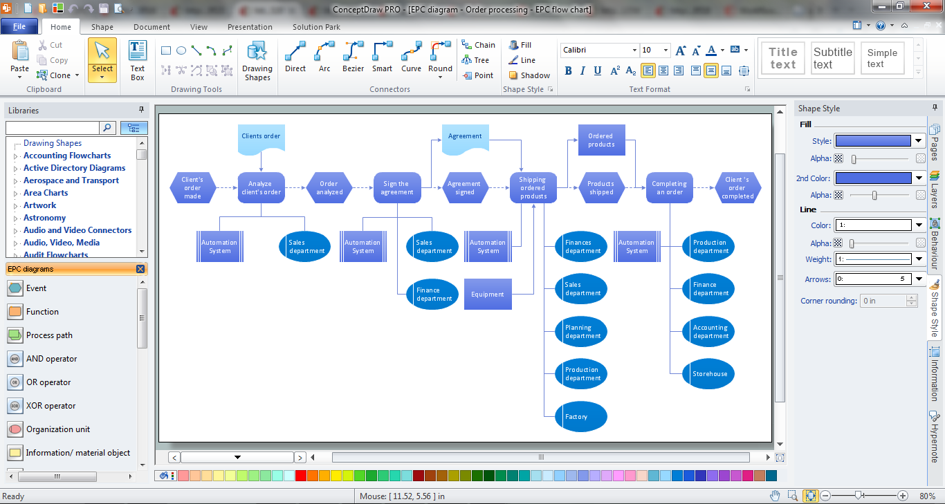
Another way of drawing any EPC diagram in ConceptDraw DIAGRAM is to use as the base the predesigned template or sample. The whole collection of them is available from ConceptDraw STORE.

Example 3. EPC Diagram Template
The sample and template you see on this page were created in ConceptDraw DIAGRAM using the Event-driven Process Chain Diagrams EPC Solution for ConceptDraw DIAGRAM They successfully demonstrate solution's capabilities and professional results you can achieve, and are available from ConceptDraw STORE.
Use the EPC IT Solutions for fast and easy creating the EPC diagrams of any complexity, and then successfully use them in your work activity.
All source documents are vector graphic documents. They are available for reviewing, modifying, or converting to a variety of formats (PDF file, MS PowerPoint, MS Visio, and many other graphic formats) from the ConceptDraw STORE. The Event-driven Process Chain Diagrams EPC Solution is available for all ConceptDraw DIAGRAM or later users.