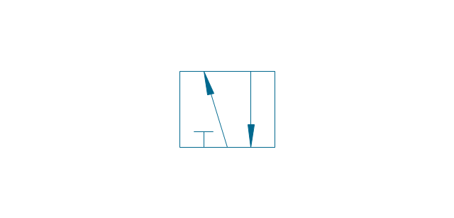
The vector stencils library "Valve assembly" contains 141 symbols of pressure and flow regulators, flow direction indicators, controls, and symbols to design flow paths of control valves.
Use these valve assembly shapes to design the engineering drawings of hydraulic and pneumatic valve assemblies in fluid power systems.
"Control valves are valves used to control conditions such as flow, pressure, temperature, and liquid level by fully or partially opening or closing in response to signals received from controllers that compare a "setpoint" to a "process variable" whose value is provided by sensors that monitor changes in such conditions.
The opening or closing of control valves is usually done automatically by electrical, hydraulic or pneumatic actuators. Positioners are used to control the opening or closing of the actuator based on electric, or pneumatic signals.
A control valve consists of three main parts in which each part exist in several types and designs: Valve's actuator, Valve's positioner, Valve's body.
" [Control valves. Wikipedia]
The shapes example "" was created using the ConceptDraw PRO diagramming and vector drawing software extended with the Mechanical Engineering solution from the Engineering area of ConceptDraw Solution Park.
Valve assembly symbols

The vector stencils library "Valve assembly" contains 141 symbols of pressure and flow regulators, flow direction indicators, controls, and symbols to design flow paths of control valves in fluid power systems.
Use these valve assembly shapes to design the engineering drawings of hydraulic and pneumatic valve assemblies
in the ConceptDraw PRO diagramming and vector drawing software extended with the Mechanical Engineering solution from the Engineering area of ConceptDraw Solution Park.
www.conceptdraw.com/ solution-park/ engineering-mechanical
2 position 2,3,4 port (fin. pos.)
-valve-assembly---vector-stencils-library.png--diagram-flowchart-example.png)
2 position 2,3,4 port (infin. pos.)
-valve-assembly---vector-stencils-library.png--diagram-flowchart-example.png)
2 position 2,3,4 port (ext., fin.pos.)
-valve-assembly---vector-stencils-library.png--diagram-flowchart-example.png)
2 position 2,3,4 port (ext., infin. pos.)
-valve-assembly---vector-stencils-library.png--diagram-flowchart-example.png)
2 position 5 port (fin. pos.)
-valve-assembly---vector-stencils-library.png--diagram-flowchart-example.png)
2 position 5 port (infin. pos.)
-valve-assembly---vector-stencils-library.png--diagram-flowchart-example.png)
2 position 5 port (ext., fin.pos.)
-valve-assembly---vector-stencils-library.png--diagram-flowchart-example.png)
2 position 5 port (ext., infin. pos.)
-valve-assembly---vector-stencils-library.png--diagram-flowchart-example.png)
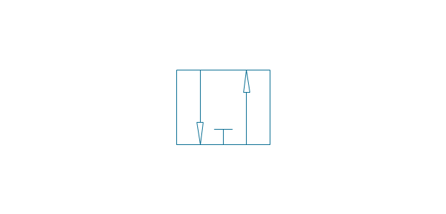
3 position 2,3,4 port (fin. pos.)
-valve-assembly---vector-stencils-library.png--diagram-flowchart-example.png)
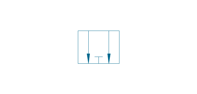
3 position 2,3,4 port (infin. pos.)
-valve-assembly---vector-stencils-library.png--diagram-flowchart-example.png)
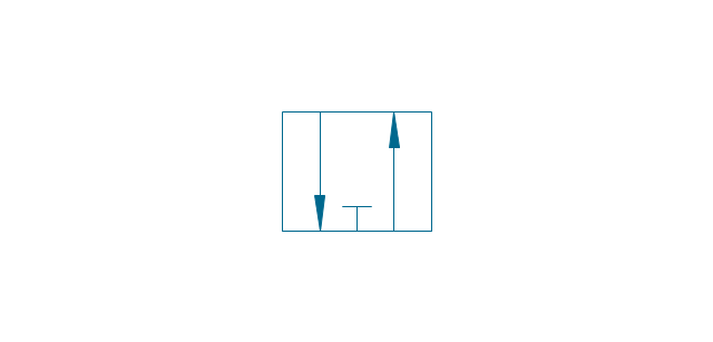
3 position 2,3,4 port (ext., fin.pos.)
-valve-assembly---vector-stencils-library.png--diagram-flowchart-example.png)
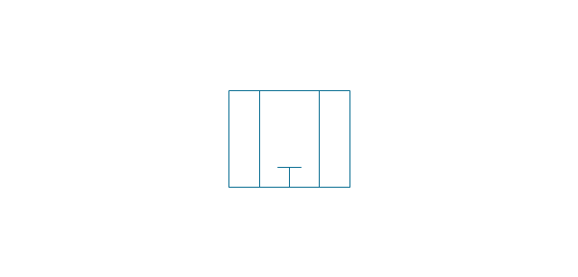
3 position 2,3,4 port (ext., infin. pos.)
-valve-assembly---vector-stencils-library.png--diagram-flowchart-example.png)
3 position 5 port (fin. pos.)
-valve-assembly---vector-stencils-library.png--diagram-flowchart-example.png)
3 position 5 port (infin. pos.)
-valve-assembly---vector-stencils-library.png--diagram-flowchart-example.png)
3 position 5 port (ext., fin.pos.)
-valve-assembly---vector-stencils-library.png--diagram-flowchart-example.png)
3 position 5 port (ext., infin. pos.)
-valve-assembly---vector-stencils-library.png--diagram-flowchart-example.png)
4 position 2,3,4 port (fin. pos.)
-valve-assembly---vector-stencils-library.png--diagram-flowchart-example.png)
4 position 2,3,4 port (infin. pos.)
-valve-assembly---vector-stencils-library.png--diagram-flowchart-example.png)
4 position 2,3,4 port (ext., fin.pos.)
-valve-assembly---vector-stencils-library.png--diagram-flowchart-example.png)
4 position 2,3,4 port (ext., infin. pos.)
-valve-assembly---vector-stencils-library.png--diagram-flowchart-example.png)
4 position 5 port (fin. pos.)
-valve-assembly---vector-stencils-library.png--diagram-flowchart-example.png)
4 position 5 port (infin. pos.)
-valve-assembly---vector-stencils-library.png--diagram-flowchart-example.png)
4 position 5 port (ext., fin.pos.)
-valve-assembly---vector-stencils-library.png--diagram-flowchart-example.png)
4 position 5 port (ext., infin. pos.)
-valve-assembly---vector-stencils-library.png--diagram-flowchart-example.png)
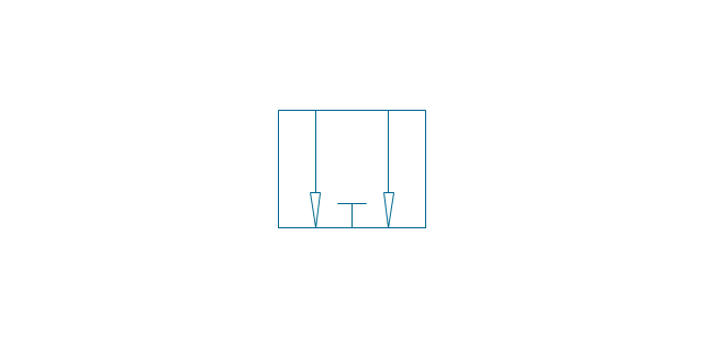
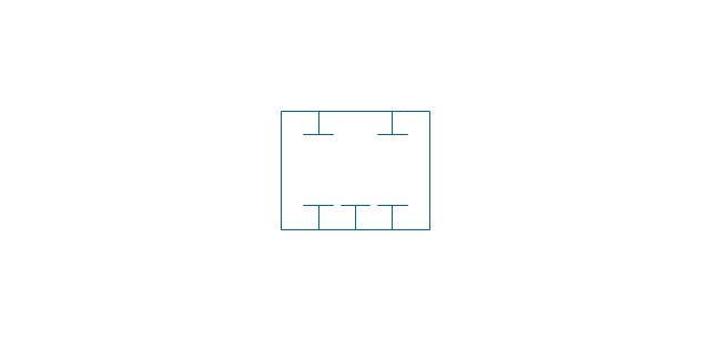
Box 5 port

Box 2,3,4 port

2-port, pneum., 1 arrow
2-port, pneum., 2 arrows

2-port, hydr., 1 arrow
2-port, hydr., 2 arrows

2-port

2-port closed

3-port, pneum., 1 arrow
3-port, pneum., 2 arrows
3-port, hydr., 1 arrow
3-port, hydr., 2 arrows
3-port
3-port crossover, pneum., 1 arrow
3-port crossover, pneum., 2 arrows
3-port crossover, hydr., 1 arrow
3-port crossover, hydr., 2 arrows

3-port crossover

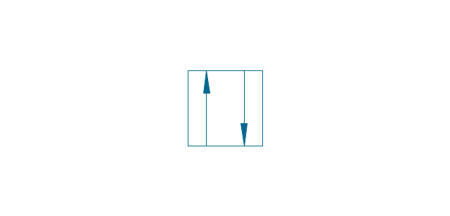
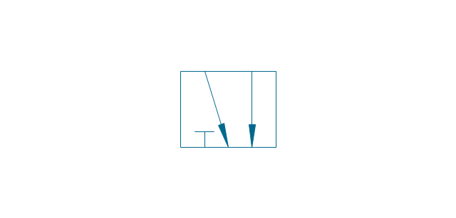
4-port, pneum.
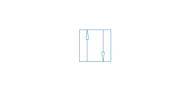
4-port, hydr.
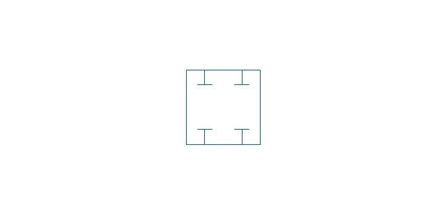
4-port closed
4-port crossed, pneum.

4-port crossed, hydr.

4-port tandem, pneum., 1 arrow
4-port tandem, pneum., 2 arrows
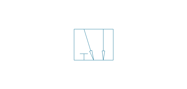
4-port tandem, hydr., 1 arrow
4-port tandem, hydr., 2 arrows
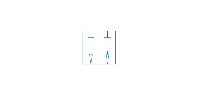
4-port tandem
4-port open
4-port semi-connected
4-port crossover, pneum., 1 arrow
4-port crossover, pneum., 2 arrows
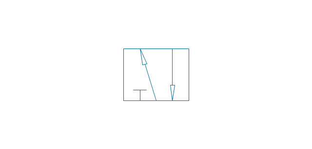
4-port crossover, hydr., 1 arrow
4-port crossover, hydr., 2 arrows
4-port crossover
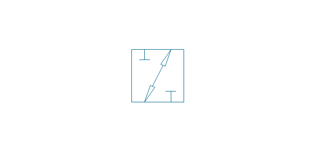
5-port, pneum., arrows same
5-port, pneum., arrows opposite
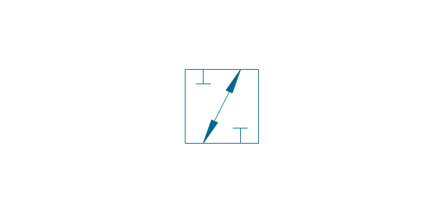
5-port, hydr., arrows same
5-port, hydr., arrows opposite
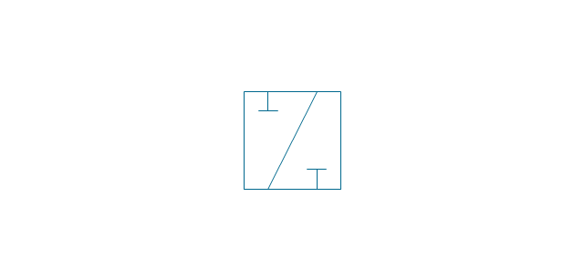
5-port
5-port closed
5-port crossover, pneum., arrows same
5-port crossover, pneum., arrows opposite
5-port crossover, hydr., arrows same
5-port crossover, hydr., arrows opposite
5-port crossover
Spring

Spring, var.

Plunger

Plunger, var.
Roller

Roller (arrow)
-valve-assembly---vector-stencils-library.png--diagram-flowchart-example.png)
One-way trip
One-way trip (arrow)
-valve-assembly---vector-stencils-library.png--diagram-flowchart-example.png)
Manual override

Pull button

Push button

Pull/push button

Lever
Pedal

Treadle

Electric rotor
Electric control, proportional, 1 winding
Electric control, proportional, 2 windings

Electric control, non-proportional, 1 winding

Electric control, non-proportional, 2 windings

Pilot-operated, pneum., 1 arrow, points left

Pilot-operated, pneum., 1 arrow, points right

Pilot-operated, pneum., 2 arrows, points left

Pilot-operated, pneum., 2 arrows, points right

Pilot-operated, pneum.

Pilot-operated, hydr., 1 arrow, points left

Pilot-operated, hydr., 1 arrow, points right

Pilot-operated, hydr., 2 arrows, points left

Pilot-operated, hydr., 2 arrows, points right

Pilot-operated, hydr.

Detent

Junction dot

T-junction, con.

T-junction, discon.

4-way junction, con.
4-way junction, discon.

Crossing
Flexible line
Air bleed, continuous

Air bleed, temporary

Fluid energy

Fluid energy, hydr.

Fluid energy, pneum.

Air exhaust port

Fluid flow, pneum.
Fluid flow, hydr.

Rotary connection (1)
-valve-assembly---vector-stencils-library.png--diagram-flowchart-example.png)
Rotary connection (3)
-valve-assembly---vector-stencils-library.png--diagram-flowchart-example.png)
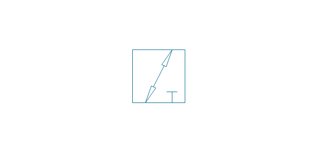
Variable arrow
Curved arrow, top

Curved arrow, bottom

Curved arrow, both ends

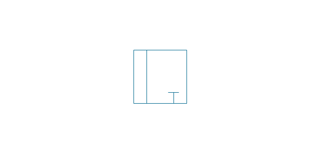
Flow path

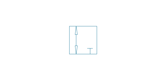
Flow path, pneum., 1 arrow
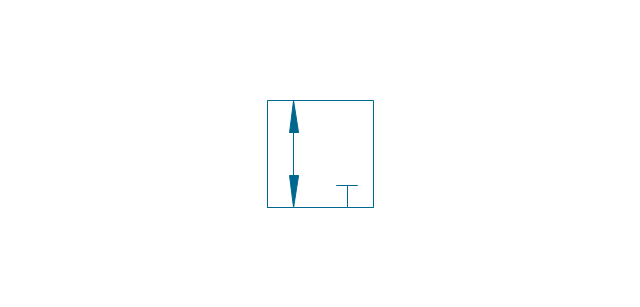
Flow path, hydr., 1 arrow
Flow path, pneum., 2 arrows

Flow path, hydr., 2 arrows

Shaft, top arrow
Shaft, bottom arrow
Shaft, both arrows

Shaft

Rod, right arrow
Rod, left arrow
Rod, both arrows

Over - center

Latch
Closed path

Electric

Restriction

Closed path (double)
-valve-assembly---vector-stencils-library.png--diagram-flowchart-example.png)
Temperature

 Mechanical Engineering
This solution extends ConceptDraw PRO v.9 mechanical drawing software (or later) with samples of mechanical drawing symbols, templates and libraries of design elements, for help when drafting mechanical engineering drawings, or parts, assembly, pneumatic,
Mechanical Engineering

Mechanical Drawing Symbols

Technical Drawing Software

Mechanical Design Software

 Engineering
This solution extends ConceptDraw PRO v9.4 with the ability to visualize industrial systems in electronics, electrical, chemical, process, and mechanical engineering.
"Directional control valves are one of the most fundamental parts in hydraulic machinery as well and pneumatic machinery. They allow fluid flow into different paths from one or more sources. They usually consist of a spool inside a cylinder which is mechanically or electrically controlled. The movement of the spool restricts or permits the flow, thus it controls the fluid flow." [Directional control valve. Wikipedia]
This example engineering drawing showing the directional control valve usage with fixed volume pump and hydraulic cylinder is redesigned using the ConceptDraw PRO diagramming and vector drawing software from Wikimedia Commons file: DCV 19.jpg.
[commons.wikimedia.org/ wiki/ File:DCV_ 19.jpg]
This file is licensed under the Creative Commons Attribution-Share Alike 3.0 Unported license.
[creativecommons.org/ licenses/ by-sa/ 3.0/ deed.en]
The fluid power equipment drawing example "Directional control valve" is included in the Mechanical Engineering solution from the Engineering area of ConceptDraw Solution Park.
Hydraulic equipment schematic

The vector stencils library "Laboratory equipment" contains 31 clipart icons of chemical laboratory equipment and labware.
Use these shapes for drawing part assembly and mounting schemes of glassware apparatus in chemical experiment diagrams and illustrations in the ConceptDraw PRO diagramming and vector drawing software extended with the Chemistry solution from the Science and Education area of ConceptDraw Solution Park.
Use these shapes for drawing part assembly and mounting schemes of glassware apparatus in chemical experiment diagrams and illustrations in the ConceptDraw PRO diagramming and vector drawing software extended with the Chemistry solution from the Science and Education area of ConceptDraw Solution Park.
Vigreux distillation column

Hirsch funnel

Oil bath

Steam bath

Thermometer

Tap (valve)
--laboratory-equipment---vector-stencils-library.png--diagram-flowchart-example.png)
Vacuum adaptor

Liebig condenser (long)
-laboratory-equipment---vector-stencils-library.png--diagram-flowchart-example.png)
Liebig condenser (short)
-laboratory-equipment---vector-stencils-library.png--diagram-flowchart-example.png)
Water faucet

Büchner flask

Stemless funnel

Stemmed funnel

Separatory funnel

Heating mantle

Hot plate

Gas tap

Folded filter paper

Y-Adaptor

Claisen adapter

Bunsen burner

Büchner funnel

Erlenmeyer flask, 25ml

Round-bottom flask, 50ml

Round-bottom flask, 250ml

Beaker 100ml, filled

Beaker 100ml, empty

Beaker 500ml, filled

Beaker 500ml, empty

Erlenmeyer flask 250ml, filled

Erlenmeyer flask 250ml, empty

- Design elements - Valve assembly
- Design elements - Valve assembly | Valve Symbol Monitoring ...
- Mechanical Engineering | Design elements - Valve assembly ...
- Valve assembly - Vector stencils library
- Directional control valve | Design elements - Valve assembly ...
- Design elements - Fluid power valves | Design elements - Valve ...
- Pneumatic 4-ported 3-position valve template - Win | Design ...
- Design elements - Valve assembly | Interior Design Piping Plan ...
- Design elements - Valve assembly | Design elements - Fluid power ...
- Free-body diagram | Design elements - Fluid power valves | Design ...
- Design elements - Valve assembly | Design elements - Terminals ...
- Types Of Valves And Symbols
- Engineering | Technical drawing - Machine parts assembling ...
- Mechanical Valves And Symbols
- Design elements - Valves and fittings
- Valves - Vector stencils library | Design elements - Valve assembly ...
- Design elements - Valve assembly
- Design elements - Valves | Pneumatic 5-ported 3-position valve ...
- Visio Files and ConceptDraw | Doors - Vector stencils library ...
- Solutions Of Assembly Drawings