ConceptDraw PRO UML Diagrams with ConceptDraw PRO

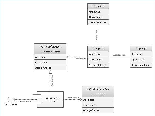
"In software engineering, a class diagram in the Unified Modeling Language (UML) is a type of static structure diagram that describes the structure of a system by showing the system's classes, their attributes, operations (or methods), and the relationships among objects. ...
The class diagram is the main building block of object oriented modelling. It is used both for general conceptual modelling of the systematics of the application, and for detailed modelling translating the models into programming code. Class diagrams can also be used for data modeling. The classes in a class diagram represent both the main objects, interactions in the application and the classes to be programmed." [Class diagram. Wikipedia]
The template "UML class diagram" for the ConceptDraw PRO diagramming and vector drawing software is included in the Rapid UML solution from the Software Development area of ConceptDraw Solution Park.
www.conceptdraw.com/ solution-park/ software-uml
UML class diagram
HelpDesk
How to Make a UML Diagram in ConceptDraw PRO

- Business Process Modeling with ConceptDraw | UML Business ...
- UML Sample Project | UML 2 4 Process Flow Diagram | UML Use ...
- UML Notation | Business Process Modeling with ConceptDraw ...
- UML Diagram | Unified Modeling Language Diagram | Design ...
- UML Diagrams with ConceptDraw PRO | Business Process ...
- Business Process Modeling with ConceptDraw | UML Business ...
- UML Class Diagram Generalization Example | Rapid UML | UML ...
- UML Business Process | Business Process Modeling with ...
- UML Activity Diagram | Diagramming Software for Design UML ...
- UML Diagram | Rapid UML | UML Use Case Diagrams | Uml ...
- UML Notation
- Business Process Modeling Notation Template | Business Process ...
- UML Diagram | Unified Modeling Language Diagram | UML ...
- Rapid UML | Introductory Guide to Rapid UML Solution | UML ...
- Rapid UML | Total Quality Management with ConceptDraw | Data ...
- Business Process Modeling with ConceptDraw | UML Diagrams with ...
- Rapid UML | ConceptDraw Solution Park | UML Diagram of Parking ...
- UML Diagram | Unified Modeling Language Diagram | ConceptDraw ...
- UML Diagram | Unified Modeling Language Diagram | ConceptDraw ...
- UML Diagram | Unified Modeling Language Diagram | Design ...