Work Order Process Flowchart. Business Process Mapping Examples
The business process is a set of actions or tasks which are undertaken by an organization for production some goods or services, they are then offered for the customers and are ordered by them. Process Flowcharts and Order Process Flowcharts are sufficiently prevalent, well known and actively used in variety of fields of life, business and science. They are constructed using the common standardized symbols, thus are clear and understandable for all. They help effectively represent the processes, determine the order in which the process activities happen, document the order processes, and also effectively analyze the processes with a goal to increase their efficiency. Create your own Process Flowcharts, Order Process Flowcharts, Cross-Functional Flow Charts representing the order processing steps using powerful drawing tools of ConceptDraw DIAGRAM software and variety of predesigned vector objects from the libraries of Business Process Mapping Solution from Business Processes area of ConceptDraw Solution Park.
 Business Process Diagrams
Business Process Diagrams solution extends the ConceptDraw DIAGRAM BPM software with RapidDraw interface, templates, samples and numerous libraries based on the BPMN 1.2 and BPMN 2.0 standards, which give you the possibility to visualize equally easy simple and complex processes, to design business models, to quickly develop and document in details any business processes on the stages of project’s planning and implementation.
 Stakeholder Onion Diagrams
The Stakeholder Onion Diagram is often used as a way to view the relationships of stakeholders to a project goal. A basic Onion Diagram contains a rich information. It shows significance of stakeholders that will have has influence to the success achieve
Organizational Chart Templates
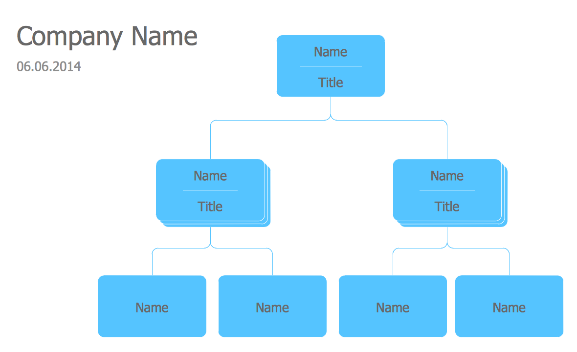
ConceptDraw offers you a number of ready-made organizational chart templates which you can use in your drawing. They are grouped in topical sets as organizational chart template files. Use the Organizational Charts Solution for ConceptDraw DIAGRAM to create your own Organizational Charts of any complexity quick, easy and effective. The Organizational Charts designed with ConceptDraw DIAGRAM are vector graphic documents and are available for reviewing, modifying, converting to a variety of formats (image, HTML, PDF file, MS PowerPoint Presentation, Adobe Flash or MS Visio XML), printing and send via e-mail in one moment.
UML Sample Project
Unified Modeling Language (UML) is a graphical modeling language for describing, visualizing, projecting and documenting of object oriented systems. UML digram is used for modeling of organizations and their business processes, for development the big projects, the complex software applications. Comprehensive UML diagram allows to create the set of interrelated documents that gives the complete visual representation of the modeling system.- Partnership Firm Process And Procedure Image
- Partnership Firm Process And Procedure Pdf
- Partnership Firm Process And Procedure For Diagram And Chart
- Partnership Firm Process And Proceder Project Pdf Download
- Partnership Firm Process And Procedure Project Analysis
- Partnership Firm Process And Procedure Project
- Information Of Patnership Firm Process
- Partnership Firm Process And Procedure Full Project Pdf
- Partnership Firm Diagram
- A Report On Procedure Of Partnership Firm Data And Information
- Organisation Chart Of Partnership Firm
- Flow chart Example. Warehouse Flowchart | Business Process ...
- Orgchart | Successful Strategic Plan | Organizational Charts with ...
- Process Flowchart | Flow chart Example. Warehouse Flowchart ...
- Partnership Firm Process Information Images
- How to Draw an Organization Chart | Examples of Flowcharts , Org ...
- How to Draw an Organization Chart | Examples of Flowcharts , Org ...
- Process Flowchart | Data Flow Diagram | Structured Systems ...
- Audit Process Flowchart. Audit Flowchart | How to Create an Audit ...


