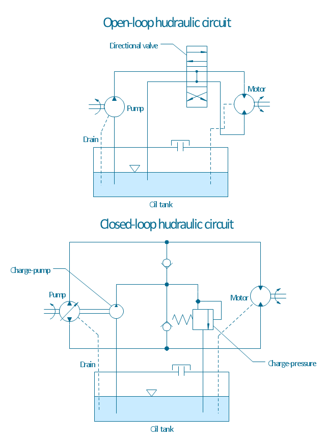
"A hydraulic circuit is a system comprising an interconnected set of discrete components that transport liquid. The purpose of this system may be to control where fluid flows (as in a network of tubes of coolant in a thermodynamic system) or to control fluid pressure (as in hydraulic amplifiers).
... hydraulic circuit theory works best when the elements (passive component such as pipes or transmission lines or active components such as power packs or pumps) are discrete and linear. This usually means that hydraulic circuit analysis works best for long, thin tubes with discrete pumps, as found in chemical process flow systems or microscale devices." [Hydraulic circuit. Wikipedia]
The engineering drawing example "Hydraulic circuits" was redrawn using ConceptDraw PRO diagramming and vector drawing software from the Wikimedia Commons file: Hydraulic circuits.png.
[commons.wikimedia.org/ wiki/ File:Hydraulic_ circuits.png]
This file is licensed under the Creative Commons Attribution-Share Alike 3.0 Unported license.
[creativecommons.org/ licenses/ by-sa/ 3.0/ deed.en]
The engineering drawing example "Hydraulic circuits" is included in the Mechanical Engineering solution from the Engineering area of ConceptDraw Solution Park.
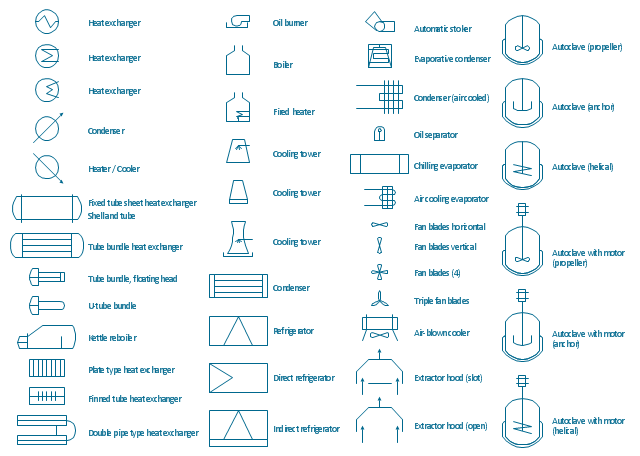
The vector stencils library "Heating equipment" contains 42 symbols of regenerators, intercoolers, heaters, and condensers.
Use these shapes for drawing cooling systems, heat recovery systems, thermal, heat transfer and mechanical design, and process flow diagrams (PFD).
"Heating or cooling of processes, equipment, or enclosed environments are within the purview of thermal engineering.
One or more of the following disciplines may be involved in solving a particular thermal engineering problem:
Thermodynamics,
Fluid mechanics,
Heat transfer,
Mass transfer.
Thermal engineering may be practiced by mechanical engineers and chemical engineers.
One branch of knowledge used frequently in thermal engineering is that of thermofluids." [Thermal engineering. Wikipedia]
The design elements example "Heating equipment" was created using the ConceptDraw PRO diagramming and vector drawing software extended with the Chemical and Process Engineering solution from the Engineering area of ConceptDraw Solution Park.
- Pumps - Vector stencils library | Thermodynamics Basic Flow Chart
- How to Draw a Chemical Process Flow Diagram
- Process Flowchart | Process Flow Diagram Symbols | How to Draw a ...
- Thermodynamics Symbol
- Process Flow Diagram Symbols | Process Flowchart | Chemical and ...
- Process Flow Diagram Symbols | Process Flowchart | How To use ...
- Mechanical Drawing Symbols | Process Flow Diagram Symbols ...
- Process Flow Diagram Symbols | Process Flowchart | Mechanical ...
- Engineering | Process Flow Diagram | Piping and Instrumentation ...
- How To Draw A Mechanical Engineering Schematics
- Flowchart design. Flowchart symbols, shapes, stencils and icons ...
- Process Flowchart | Chemical and Process Engineering | How to ...
- Mechanical Drawing Symbols | Mechanical Engineering | Flowchart ...
- Process Flow Diagram Symbols | Process Flowchart | Making ...
- Design elements - Chemical engineering | Process Flowchart ...
- Mechanical Drawing Symbols | Process Flowchart | Design ...
- How To use House Electrical Plan Software | Process Flow Diagram ...
- Process Flowchart | Chemistry Symbols and Meanings | Process ...
- Process Flow Diagram Symbols | Design elements - Heating ...
- Process Flowchart | Heating equipment - Vector stencils library ...

