The vector stencils library "Logic gate diagram" contains 17 logical element symbols.
Use these shapes for drawing the logic gate diagrams in the ConceptDraw PRO diagramming and vector drawing software extended with the Electrical Engineering solution from the Engineering area of ConceptDraw Solution Park.
www.conceptdraw.com/ solution-park/ engineering-electrical
Use these shapes for drawing the logic gate diagrams in the ConceptDraw PRO diagramming and vector drawing software extended with the Electrical Engineering solution from the Engineering area of ConceptDraw Solution Park.
www.conceptdraw.com/ solution-park/ engineering-electrical
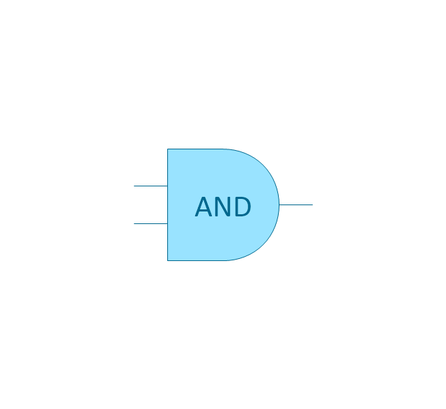
AND gate
OR gate

NOR gate (NOT OR)
-logic-gate-diagram---vector-stencils-library.png--diagram-flowchart-example.png)
NAND gate (NOT AND)
-logic-gate-diagram---vector-stencils-library.png--diagram-flowchart-example.png)
NOT gate (inverter)
-logic-gate-diagram---vector-stencils-library.png--diagram-flowchart-example.png)
EX-OR (Exclusive-OR) gate
-gate-logic-gate-diagram---vector-stencils-library.png--diagram-flowchart-example.png)
EX-NOR (Exclusive-NOR) gate
-gate-logic-gate-diagram---vector-stencils-library.png--diagram-flowchart-example.png)
Group

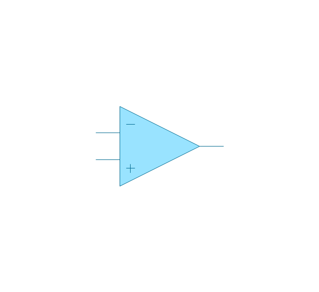
Operational Amplifier
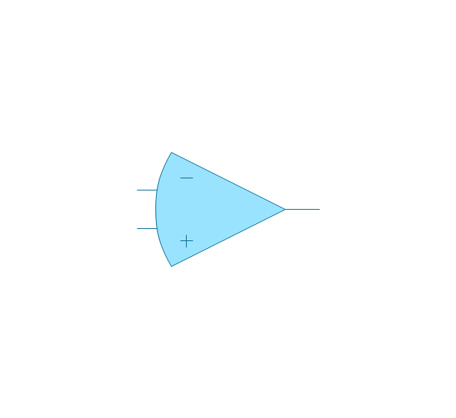
Alternative Operational Amplifier
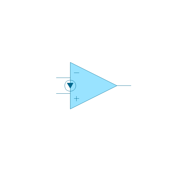
Norton op-amp
NOT gate (inverter)
-logic-gate-diagram---vector-stencils-library.png--diagram-flowchart-example.png)
NAND gate (NOT AND)
-logic-gate-diagram---vector-stencils-library.png--diagram-flowchart-example.png)
NOR gate (NOT OR)
-logic-gate-diagram---vector-stencils-library.png--diagram-flowchart-example.png)
Buffer

Gate with Open-Collector Output
Gate with Schmitt Trigger Input

The vector stencils library "Logic gate diagram" contains 17 logical element symbols.
Use these shapes for drawing the logic gate diagrams in the ConceptDraw PRO diagramming and vector drawing software extended with the Electrical Engineering solution from the Engineering area of ConceptDraw Solution Park.
www.conceptdraw.com/ solution-park/ engineering-electrical
Use these shapes for drawing the logic gate diagrams in the ConceptDraw PRO diagramming and vector drawing software extended with the Electrical Engineering solution from the Engineering area of ConceptDraw Solution Park.
www.conceptdraw.com/ solution-park/ engineering-electrical
AND gate
OR gate
NOR gate (NOT OR)
NAND gate (NOT AND)
NOT gate (inverter)
EX-OR (Exclusive-OR) gate
EX-NOR (Exclusive-NOR) gate
Group
Operational Amplifier
Alternative Operational Amplifier
Norton op-amp
NOT gate (inverter)
NAND gate (NOT AND)
NOR gate (NOT OR)
Buffer
Gate with Open-Collector Output
Gate with Schmitt Trigger Input
Electrical Symbols — Logic Gate Diagram

The vector stencils library "Instruments" contains 72 symbols of control instruments and measuring devices: meters and gauges, and callouts, text boxes, and inserts.
Use these shapes to create annotated process flow diagrams (PFD), flow control, manufacturing processes, and distribution system diagrams in the ConceptDraw PRO software extended with the Chemical and Process Engineering solution from the Chemical and Process Engineering area of ConceptDraw Solution Park.
www.conceptdraw.com/ solution-park/ engineering-chemical-process
Indicator local

Indicator remote

Indicator auxiliary

CRT local

CRT remote

CRT auxiliary

PLC local

PLC auxiliary

PLC remote

Computer local

Computer auxiliary

Computer remote

Light local

Light remote

Light auxiliary

Indicator auxiliary (dashed)
-instruments---vector-stencils-library.png--diagram-flowchart-example.png)
Indicator remote (dashed)
-instruments---vector-stencils-library.png--diagram-flowchart-example.png)
Steam traced auxiliary

Steam traced remote

Steam traced local

Level meter auxiliary

Level meter remote

Level meter local

Pressure gauge diaphragm

Pressure gauge

Pressure gauge liquid filled

Strain gauge

Thermometer bi-metallic

Thermometer gas

Thermometer general

Thermometer glass

Thermometer liquid

Thermometer resistance

Thermometer thermocouple

Flowmeter electromagnetic

Flowmeter general

Flowmeter nozzle

Flowmeter orifice

Flowmeter positive displacement

Flowmeter turbine

Flowmeter variable area

Flowmeter Venturi

Level meter capacitive

Level meter conductive

Level meter displacer

Level meter float

Level meter general

Level meter sonic

Indicator analoque

Indicator digital

Indicator general

Recorder analoque

Recorder digital

Recorder general

Converter

Converter 2 (1st half filled)
-instruments---vector-stencils-library.png--diagram-flowchart-example.png)
Converter 3 (2nd half filled)
-instruments---vector-stencils-library.png--diagram-flowchart-example.png)
Venturi

Venturi (pressure taps)
-instruments---vector-stencils-library.png--diagram-flowchart-example.png)
Flowmeter

Rotameter

Vortex sensor

Propeller meter

Generic utility

Operator box

Operator box 2 (1st half filled)
-instruments---vector-stencils-library.png--diagram-flowchart-example.png)
Operator box 3 (2nd half filled)
-instruments---vector-stencils-library.png--diagram-flowchart-example.png)
AND gate

OR gate

NOT gate

Correcting element

Diamond

The vector stencils library "Logic gate diagram" contains 17 logical element symbols.
Use these shapes for drawing the logic gate diagrams in the ConceptDraw PRO diagramming and vector drawing software extended with the Electrical Engineering solution from the Engineering area of ConceptDraw Solution Park.
www.conceptdraw.com/ solution-park/ engineering-electrical
Use these shapes for drawing the logic gate diagrams in the ConceptDraw PRO diagramming and vector drawing software extended with the Electrical Engineering solution from the Engineering area of ConceptDraw Solution Park.
www.conceptdraw.com/ solution-park/ engineering-electrical
AND gate
OR gate
NOR gate (NOT OR)
NAND gate (NOT AND)
NOT gate (inverter)
EX-OR (Exclusive-OR) gate
EX-NOR (Exclusive-NOR) gate
Group
Operational Amplifier
Alternative Operational Amplifier
Norton op-amp
NOT gate (inverter)
NAND gate (NOT AND)
NOR gate (NOT OR)
Buffer
Gate with Open-Collector Output
Gate with Schmitt Trigger Input
The vector stencils library "Instruments" contains 72 symbols of control instruments and measuring devices: meters and gauges, and callouts, text boxes, and inserts.
Use these shapes to create annotated process flow diagrams (PFD), flow control, manufacturing processes, and distribution system diagrams in the ConceptDraw PRO software extended with the Chemical and Process Engineering solution from the Chemical and Process Engineering area of ConceptDraw Solution Park.
www.conceptdraw.com/ solution-park/ engineering-chemical-process
Use these shapes to create annotated process flow diagrams (PFD), flow control, manufacturing processes, and distribution system diagrams in the ConceptDraw PRO software extended with the Chemical and Process Engineering solution from the Chemical and Process Engineering area of ConceptDraw Solution Park.
www.conceptdraw.com/ solution-park/ engineering-chemical-process
Indicator local
Indicator remote
Indicator auxiliary
CRT local
CRT remote
CRT auxiliary
PLC local
PLC auxiliary
PLC remote
Computer local
Computer auxiliary
Computer remote
Light local
Light remote
Light auxiliary
Indicator auxiliary (dashed)
Indicator remote (dashed)
Steam traced auxiliary
Steam traced remote
Steam traced local
Level meter auxiliary
Level meter remote
Level meter local
Pressure gauge diaphragm
Pressure gauge
Pressure gauge liquid filled
Strain gauge
Thermometer bi-metallic
Thermometer gas
Thermometer general
Thermometer glass
Thermometer liquid
Thermometer resistance
Thermometer thermocouple
Flowmeter electromagnetic
Flowmeter general
Flowmeter nozzle
Flowmeter orifice
Flowmeter positive displacement
Flowmeter turbine
Flowmeter variable area
Flowmeter Venturi
Level meter capacitive
Level meter conductive
Level meter displacer
Level meter float
Level meter general
Level meter sonic
Indicator analoque
Indicator digital
Indicator general
Recorder analoque
Recorder digital
Recorder general
Converter
Converter 2 (1st half filled)
Converter 3 (2nd half filled)
Venturi
Venturi (pressure taps)
Flowmeter
Rotameter
Vortex sensor
Propeller meter
Generic utility
Operator box
Operator box 2 (1st half filled)
Operator box 3 (2nd half filled)
AND gate
OR gate
NOT gate
Correcting element
Diamond
The vector stencils library "Logic gate diagram" contains 17 element symbols for drawing the logic gate diagrams.
"To build a functionally complete logic system, relays, valves (vacuum tubes), or transistors can be used. The simplest family of logic gates using bipolar transistors is called resistor-transistor logic (RTL). Unlike simple diode logic gates (which do not have a gain element), RTL gates can be cascaded indefinitely to produce more complex logic functions. RTL gates were used in early integrated circuits. For higher speed and better density, the resistors used in RTL were replaced by diodes resulting in diode-transistor logic (DTL). Transistor-transistor logic (TTL) then supplanted DTL. As integrated circuits became more complex, bipolar transistors were replaced with smaller field-effect transistors (MOSFETs); see PMOS and NMOS. To reduce power consumption still further, most contemporary chip implementations of digital systems now use CMOS logic. CMOS uses complementary (both n-channel and p-channel) MOSFET devices to achieve a high speed with low power dissipation." [Logic gate. Wikipedia]
The symbols example "Design elements - Logic gate diagram" was drawn using the ConceptDraw PRO diagramming and vector drawing software extended with the Electrical Engineering solution from the Engineering area of ConceptDraw Solution Park.
Logic gate symbols

The vector stencils library "IGFET" contains 18 symbols of IGFET (insulated-gate field-effect transistor) elements for drawing electronic circuit diagrams.
"The metal–oxide–semiconductor field-effect transistor (MOSFET, MOS-FET, or MOS FET) is a transistor used for amplifying or switching electronic signals. Although the MOSFET is a four-terminal device with source (S), gate (G), drain (D), and body (B) terminals, the body (or substrate) of the MOSFET often is connected to the source terminal, making it a three-terminal device like other field-effect transistors. Because these two terminals are normally connected to each other (short-circuited) internally, only three terminals appear in electrical diagrams. The MOSFET is by far the most common transistor in both digital and analog circuits, though the bipolar junction transistor was at one time much more common. ...
An insulated-gate field-effect transistor or IGFET is a related term almost synonymous with MOSFET. The term may be more inclusive, since many "MOSFETs" use a gate that is not metal, and a gate insulator that is not oxide. Another synonym is MISFET for metal–insulator–semiconductor FET." [MOSFET
From Wikipedia]
The symbols example "Design elements - IGFET" was drawn using the ConceptDraw PRO diagramming and vector drawing software extended with the Electrical Engineering solution from the Engineering area of ConceptDraw Solution Park.
IGFET elements

Electrical Symbols — IGFET

Fault Tree Analysis Software

HelpDesk
How to Create a Fault Tree Analysis Diagram (FTD) in ConceptDraw PRO

Electrical Symbols — MOSFET

- NOT gate (inverter)
- Logic gate diagram - Vector stencils library | Symbol Ex Nor Gate
- Logic gate diagram - Vector stencils library | Design elements ...
- Symbol Of Nand Gate Open Collector Output
- Or Gate From Nor Gate
- NOT gate
- NOR gate (NOT OR)
- NAND gate ( NOT AND)
- EX-NOR (Exclusive- NOR ) gate
- Electrical Symbols — Logic Gate Diagram | How to Create a Fault ...
- Logic gate diagram - Vector stencils library
- Draw The Traditional Symbols For And Or And Not Logic Gates
- Or And Not Gate Circuit Of Diagram
- Draw Symbols For And Or Not Gate
- Logic gate diagram - Template | Design elements - Logic gate ...
- Design elements - Logic gate diagram | 2-bit ALU - Logic gate ...
- Eletrical Diagram For Not Gate
- Design elements - Logic gate diagram | Electrical Symbols — Logic ...
- Electrical Symbols — Logic Gate Diagram | Design elements - Logic ...
- And Or Not Diagram